Omni-dualband antenna and system

a dual-band, omni-dual-band technology, applied in the direction of individual energised antenna arrays, resonant antennas, radiating elements structural forms, etc., can solve the problems of distorted radiation patterns for both bands and long antennas

Inactive Publication Date: 2005-04-07
ARC WIRELESS
View PDF16 Cites 42 Cited by
  • Summary
  • Abstract
  • Description
  • Claims
  • Application Information

AI Technical Summary

Problems solved by technology

Such vertically stacked arrays result in a long antenna.
Such side-by-side antenna arrays generally result in distorted radiation patterns for both bands in the azimuth plane due to interference effects that both antennas arrays experience from each other.

Method used


Image

  • Omni-dualband antenna and system
  • Omni-dualband antenna and system
  • Omni-dualband antenna and system

Examples


Embodiment Construction

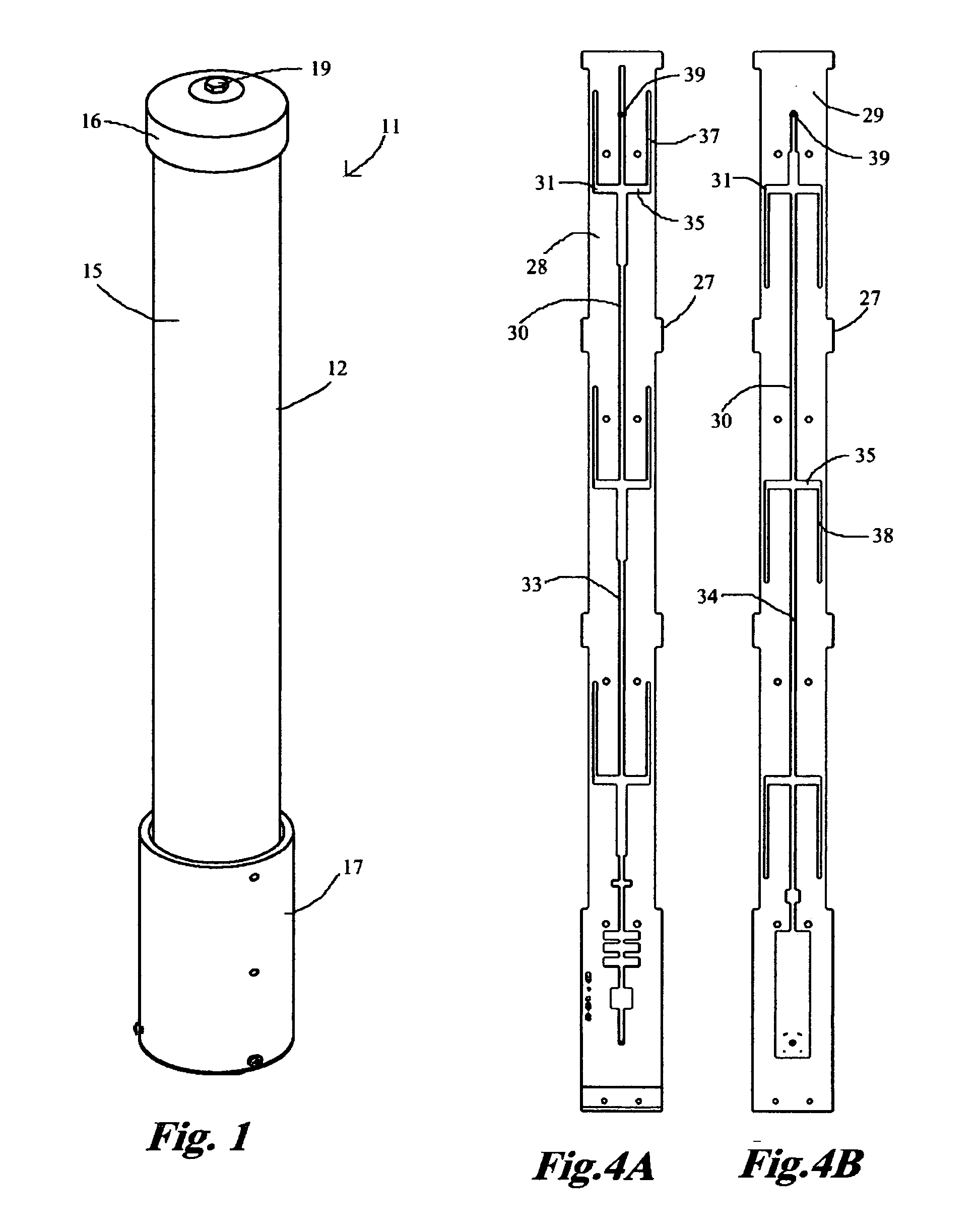
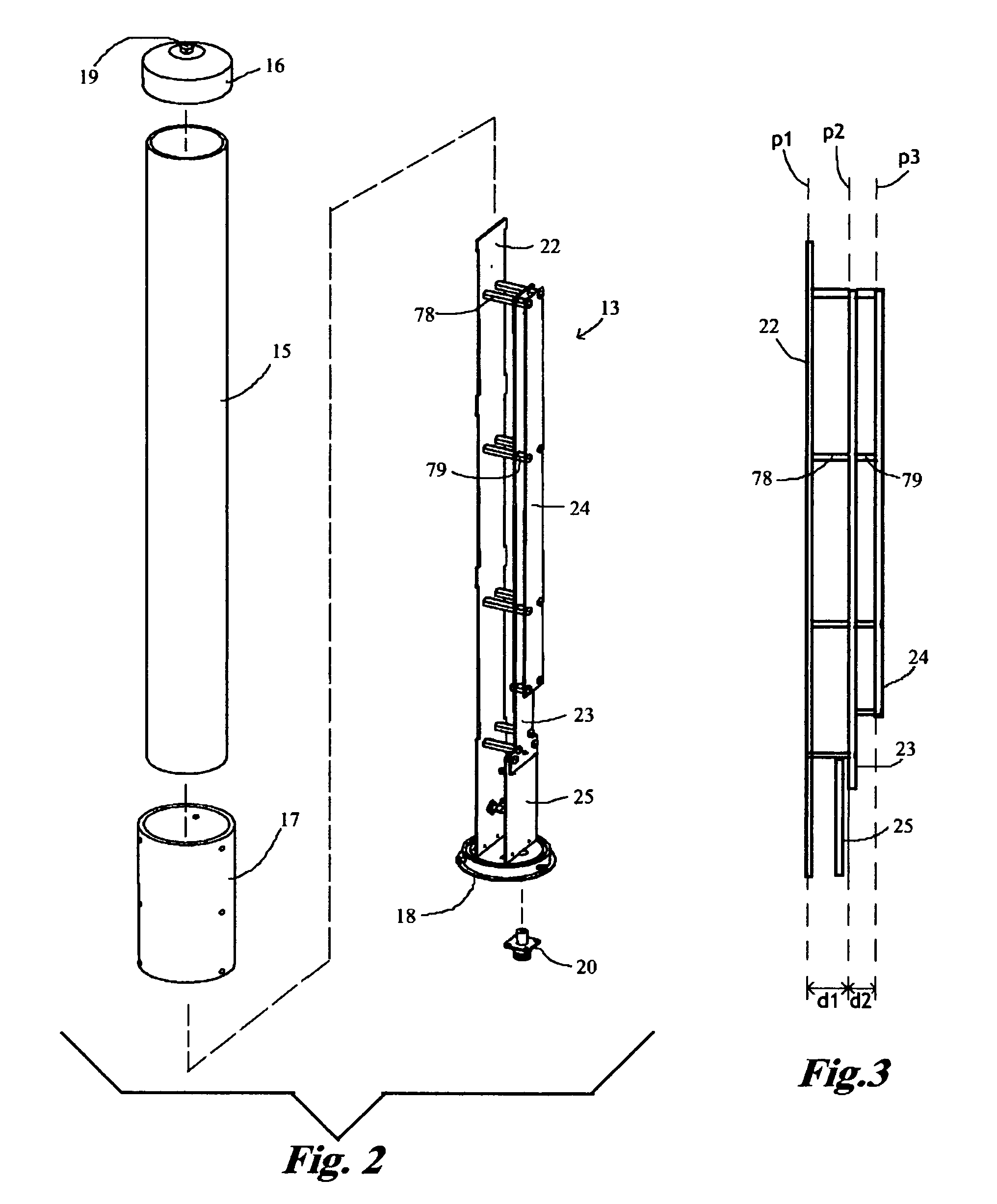
[0013] Referring to FIGS. 1 and 2, an antenna system 11 embodying features of the present invention includes a radome 12 and an antenna 13. The radome 12 has a vertically elongated, hollow, cylindrical radome tube 15, an upper radome cap 16 that fits over the upper end of the radome tube 15, a mast 17 that fits around the bottom of the radome tube 15, and a lower radome cap 18 that fits into the bottom end of the radome tube 15. A weep hole plug 19 plugs a weep hole provided in the upper radome cap 16. Connector 20 extends through the lower radome cap 18.

[0014] Describing the specific embodiments herein chosen for illustrating the invention, certain terminology is used which will be recognized as being employed for convenience and having no limiting significance. For example, the terms “horizontal”, “vertical”, “upper”, and “lower” refer to the illustrated embodiment in its normal position of use. Further, all of the terminology above-defined includes derivatives of the word specif...


PUM


Abstract

An omnidirectional dual band antenna system includes a radome and an antenna in the radome. The antenna has a linear array of lower frequency band driven elements, a linear array of higher frequency band driven elements and a linear array of parasitic elements, spaced in parallel planes with the array of higher frequency band driven elements in the middle. The parasitic elements couple to the higher frequency band driven elements and reshape the radiation pattern of the higher frequency band driven elements to correct for distortion caused by the lower frequency band driven elements.

Description

[0001] This application claims the benefit under 35 U.S.C. § 119(e) of the U.S. provisional patent application No. 60 / 507,627 filed Oct. 1, 2003.TECHNICAL FIELD [0002] The present invention relates to antennas and more particularly to a dual frequency band antenna with omni-directional radiation patterns. BACKGROUND ART [0003] Dual band omnidirectional antenna systems are useful for various wireless communications applications, particularly cellular infrastructure networks. Prior known dual band omnidirectional antenna arrays have been designed with two antenna arrays vertically stacked within a radome. Such vertically stacked arrays result in a long antenna. Other prior known dual band omnidirectional antennas, to reduce the overall length of a antenna, have two antennas arrays placed side-by-side within the same radome. Such side-by-side antenna arrays generally result in distorted radiation patterns for both bands in the azimuth plane due to interference effects that both antenna...

Claims


Application Information

Patent Timeline
Patent Type & Authority Applications(United States)
IPC IPC(8): H01Q1/38H01Q1/42H01Q5/00H01Q5/15H01Q5/42H01Q9/28H01Q21/08
CPCH01Q1/38H01Q1/42H01Q5/42H01Q21/08H01Q9/28
Inventor OLSON, STEVEN C.
Owner ARC WIRELESS
Why Eureka
Try Eureka