
Headlamp control to prevent glare

a headlamp control and glare prevention technology, applied in fixed installation, lighting and heating equipment, semiconductor devices for light sources, etc., can solve the problems of affecting the front end styling of the suv or truck, reducing the mounting height limit of the headlamps, and being difficult to reduce the mounting height significantly

Inactive Publication Date: 2005-04-07
STAM JOSEPH S
View PDF99 Cites 75 Cited by
  • Summary
  • Abstract
  • Description
  • Claims
  • Application Information

AI Technical Summary

Benefits of technology

"The present invention relates to a system for controlling the exterior lights of a vehicle. The system includes an array of sensors that detect light levels in front of the vehicle and a control unit that analyzes the sensor data and determines the distance and angle of the vehicle's exterior lights. The control unit is able to adjust the lights based on the sensor data and prevent glare to drivers of leading vehicles. The system can also include an imaging system that obtains images of the front of the vehicle and a spatially controlled variable attenuating filter or reflector to control the illumination range of the vehicle's exterior lights. The technical effects of the invention include improved control of vehicle exterior lights to avoid glare and improve visibility for drivers."

Problems solved by technology

This glare may be especially disruptive in busy traffic situations where an SUV or truck is following a small passenger car.
Unfortunately, solutions such as reducing the mounting height limit of an SUV or truck's headlamps may generally require an objectionable change to the front end styling of the SUV or truck.
Additionally, the physical construction of large SUVs and trucks may make it impossible to reduce the mounting height significantly.

Method used


Image

  • Headlamp control to prevent glare
  • Headlamp control to prevent glare
  • Headlamp control to prevent glare

Examples


Embodiment Construction

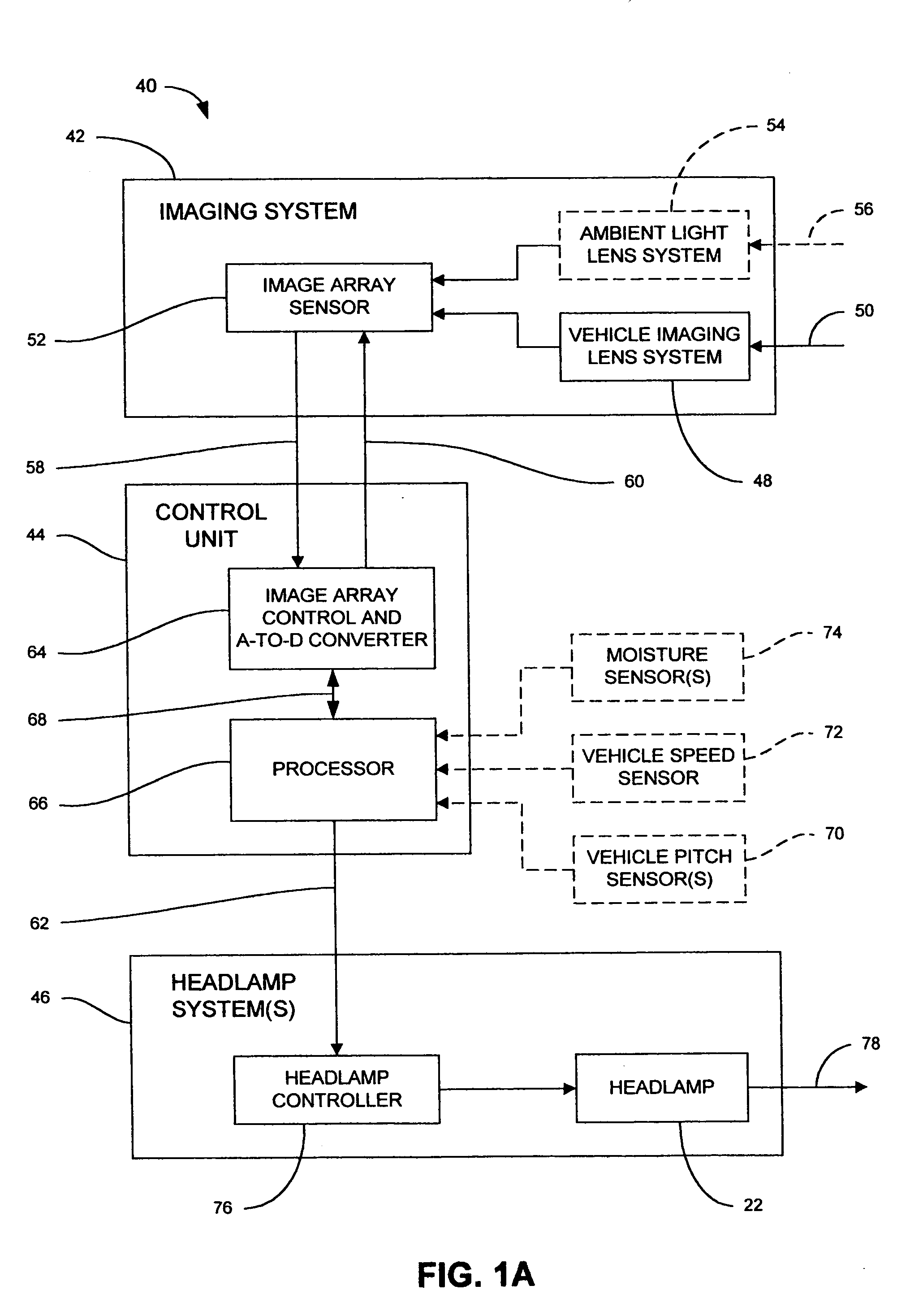
[0040] The present invention is directed to a system for controlling at least one exterior vehicle light (e.g., low-beam headlamps, high-beam headlamps, tail lamps, fog lamps, etc.) of a controlled vehicle and includes an array of sensors and a control unit. The control unit is in communication with the array of sensors and the at least one exterior vehicle light and is capable of determining a distance and an angle from the at least one exterior vehicle light of the controlled vehicle to a leading vehicle. The control unit is operable to control operation of the at least one exterior vehicle light as a function of the distance and angle, based on the output from the array of sensors, and prevent the at least one exterior vehicle light from providing disruptive glare to a driver of the leading vehicle.

[0041] In another embodiment of the present invention, an illumination control system for controlling the at least one exterior vehicle light of a controlled vehicle includes an array...


PUM


Abstract

A system for controlling at least one exterior vehicle light of a controlled vehicle includes an array of sensors and a control unit. The array of sensors is capable of detecting light levels in front of the controlled vehicle. The control unit is in communication with the array of sensors and the at least one exterior vehicle light and determines a distance and an angle from the at least one exterior vehicle light of the controlled vehicle to a leading vehicle. The control unit is operable to control operation of the at least one exterior vehicle light as a function of the distance and angle, based on the output from the array of sensors, and prevent the at least one exterior vehicle light from providing a disruptive glare to a driver of the leading vehicle.

Description

CROSS-REFERENCE TO RELATED APPLICATIONS [0001] This application is a continuation of U.S. patent application Ser. No. 10 / 253,476, filed on Sep. 5, 2002, entitled “HEADLAMP CONTROL TO PREVENT GLARE,” which claims the benefit of U.S. Provisional Patent Application Ser. No. 60 / 339,762, entitled “HEADLAMP CONTROL TO PREVENT GLARE,” which was filed Dec. 10, 2001, and which is hereby incorporated herein by reference in its entirety. [0002] This application is a continuation-in-part of U.S. patent application Ser. No. 10 / 197,834, entitled “CONTINUOUSLY VARIABLE HEADLAMP CONTROL,” filed Jul. 18, 2002, now U.S. Pat. No. 6,593,698, which is a continuation of U.S. patent application Ser. No. 09 / 938,774, entitled “CONTINUOUSLY VARIABLE HEADLAMP CONTROL,” filed on Aug. 24, 2001, now U.S. Pat. No. 6,429,594, which is a continuation of U.S. patent application Ser. No. 09 / 546,858, entitled “CONTINUOUSLY VARIABLE HEADLAMP CONTROL,” filed on Apr. 10, 2000, now U.S. Pat. No. 6,281,632, which is a cont...

Claims


Application Information

Patent Timeline
Patent Type & Authority Applications(United States)
IPC IPC(8): B60Q1/08B60Q1/14B60Q1/10B60Q1/18F21S8/10F21V14/00
CPCF21S48/10B60Q2300/42F21S48/171F21S48/1794F21V14/00F21Y2101/02B60Q1/085B60Q1/10B60Q1/18B60Q2300/054B60Q2300/056B60Q2300/112B60Q2300/114B60Q2300/122B60Q2300/132B60Q2300/21B60Q2300/312B60Q2300/314B60Q2300/322B60Q2300/331B60Q2300/332B60Q2300/3321B60Q2300/334B60Q2300/41F21S48/115F21Y2115/10F21S41/62F21S41/698F21V9/40F21S41/148F21S41/151F21S41/321F21S41/67F21S41/692F21S41/675F21W2102/135F21S41/645F21S41/43F21S41/25F21W2102/13F21S41/47F21S41/686F21S41/162F21S41/13F21S41/141F21S41/172F21S41/143F21S41/68F21S41/285F21S41/40F21S41/153F21S41/00
Inventor STAM, JOSEPH S.
Owner STAM JOSEPH S
Learn More