

Fixing device and image forming apparatus including the same
a technology of fixing device and image forming apparatus, which is applied in the direction of electrographic process apparatus, thin material processing, instruments, etc., can solve the problems of inability to meet the needs of high-speed machines, such as needing additional power, and the temperature of the heat roller, so as to reduce the warm-up time
- Summary
- Abstract
- Description
- Claims
- Application Information
AI Technical Summary
Benefits of technology
Problems solved by technology
Method used
Image

Examples
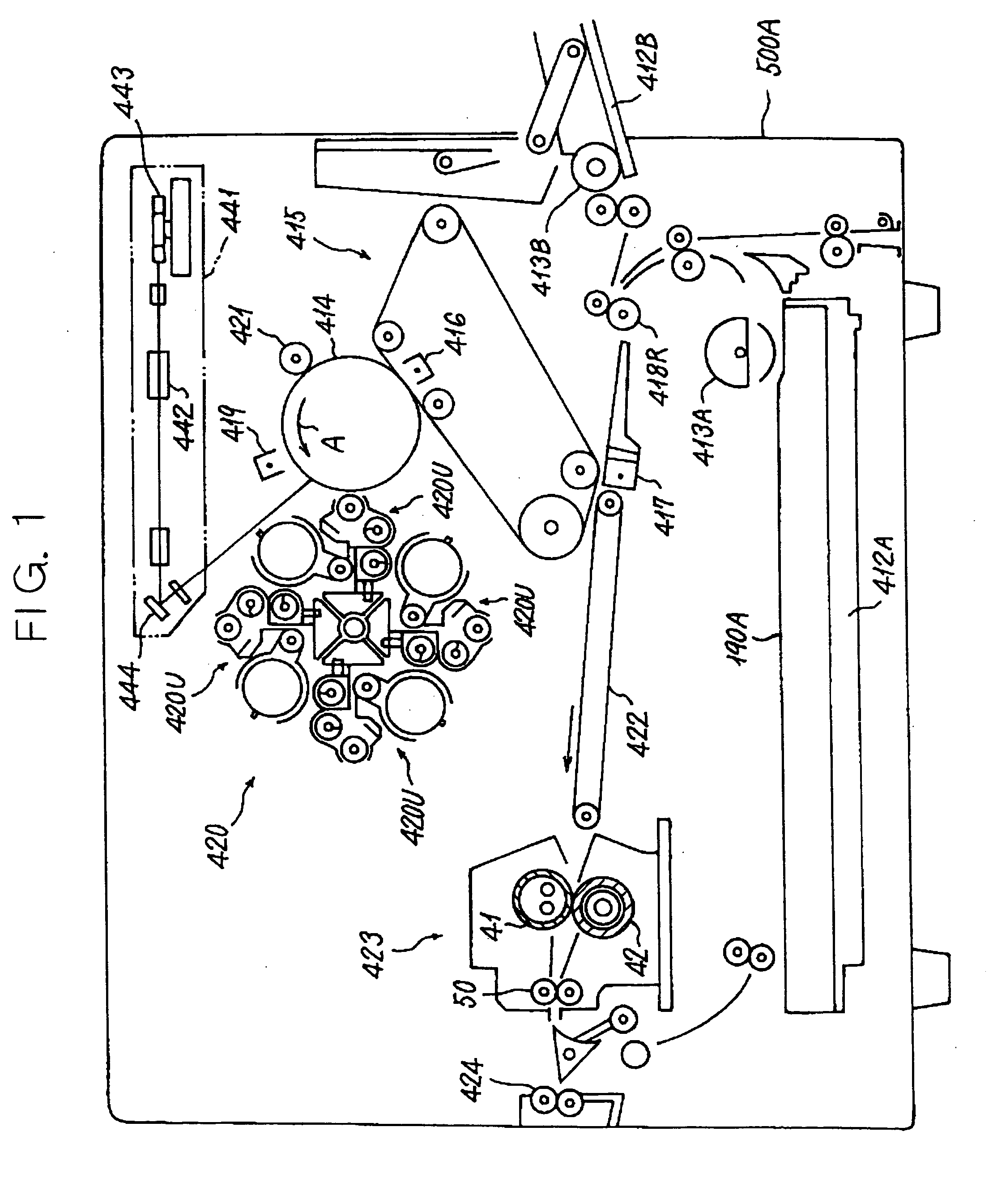
first embodiment
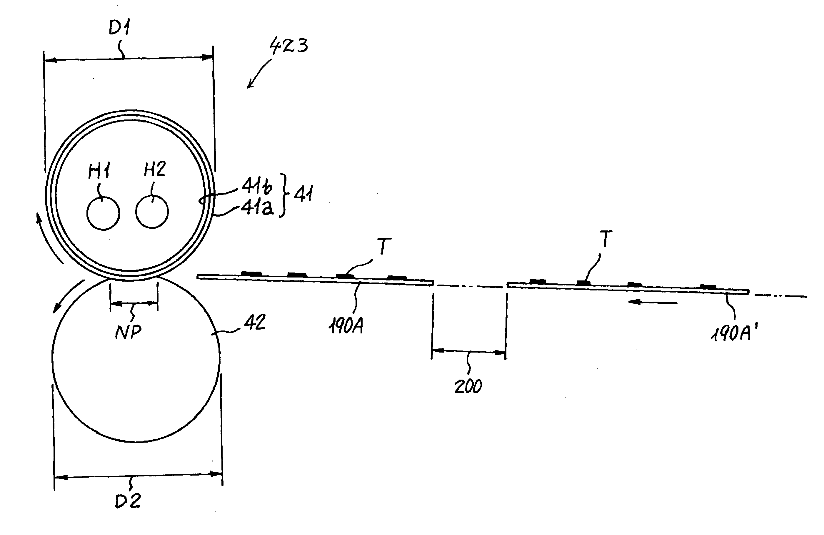
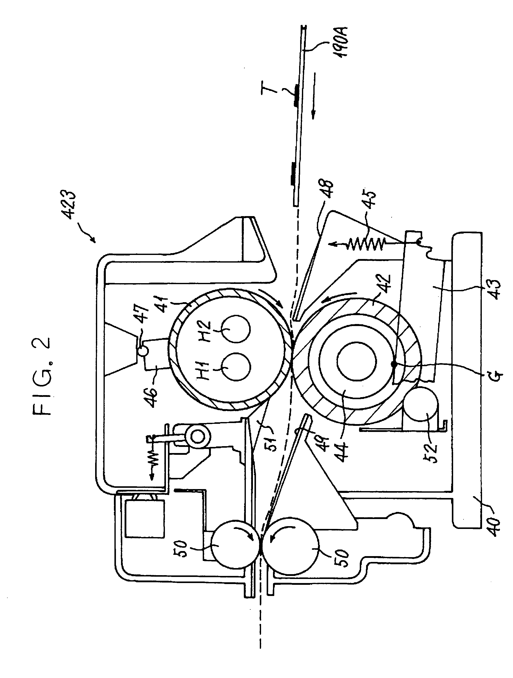
[0039] Reference will be made to FIG. 2 for describing the fixing device 423 in accordance with the present invention. As shown, the fixing device 423 includes a casing 40 and a heat roller or fixing member 41 and a press roller or pressing member 42 disposed in the casing 40. The heat roller 41 is journalled to opposite side walls, not shown, of the casing 40 in the upper portion of the casing 40. Likewise, the press roller 42 is journalled to the side walls of the casing 40 in the lower portion of the casing 40 via bearings 44 (only one is visible). Each bearing 44 is constantly biased upward by a lever 43, which is biased by a tension spring 45 about is one end, via a contact point G. Consequently, as shown in FIG. 3, the press roller 42 is pressed against the heat roller 41 over a nip having a width NP and is rotated by the heat roller 41 or driven to follow the rotation of the heat roller 41.
[0040] At least the surface of the press roller 42 is formed of an elastic material. Th...
second embodiment
[0184] More specifically, in the present invention shown in FIG. 12, an endless heat-resistant film 41-1 is passed over a drive roller 71 and a driven roller 70 as a fixing member. The driven roller 70, playing the role of a tension roller at the same time, applies tension to the film 41-1. The drive roller 71 causes the film 41-1 to move in a direction indicated by arrows. To reduce thermal capacity, the film 41-1 is provided with total thickness as small as 100 μm or below and implemented as a laminate made up of a polyimide or similar durable, heat-resistant film having parting ability and a PTFE coated on the film as a parting layer.
[0185] The press roller 42 faces a heater or heat source 72 with the intermediary of the film 41-1 and is rotated by the film 41-1 while pressing the film 41-1 against the heater 72. The heater 72 is an electric heater similar to the heat sources H1 and H2. When the sheet 190A, carrying the toner T thereon, is conveyed via the nip NP, the toner T is ...
third embodiment
[0186]FIG. 13 shows the present invention in which an endless belt or fixing member 41-2 is passed over a roller 73 and a heat roller 74 accommodating a heat source therein. The press roller 42 is pressed against the roller 73 via the belt 41-2. The toner T on the sheet 190A is fixed by heat when the sheet 190A is conveyed via the nip between the belt 41-2 and the press roller 42.
[0187] To reduce thermal capacity, the belt 41-2 is made up of a nickel base as thin as 100 μm and a 200 μm parting layer formed on the base by use of silicone rubber. Again, a thermistor, not shown, adjoins the surface of the belt 41-2 or that of the press roller 42 for measuring temperature at the nip between the belt 41-2 and the press roller 42.
PUM
 Abstract
Description
Claims
Application Information