
Connecting mechanism and apparatus using the same

a technology of connecting mechanism and connecting rod, which is applied in the direction of fastening means, metal-working hand tools, couplings, etc., can solve the problems of increasing the number of elements required labor, increasing fabrication time and cost, etc., and achieve the effect of reducing costs

Inactive Publication Date: 2005-04-07
ASUSTEK COMPUTER INC
View PDF8 Cites 14 Cited by
  • Summary
  • Abstract
  • Description
  • Claims
  • Application Information

AI Technical Summary

Benefits of technology

[0005] Accordingly, an object of the invention is to provide a connecting mechanism combining two work pieces without use of screws, thus reducing costs.
[0006] Another object of the invention is to provide a connecting mechanism to simplify assembly steps and shorten fabrication time.
[0007] A third object of the invention is to provide a connecting mechanism without use of screws, such that a product with the connecting mechanism of the invention can be more easily assembled automatically.
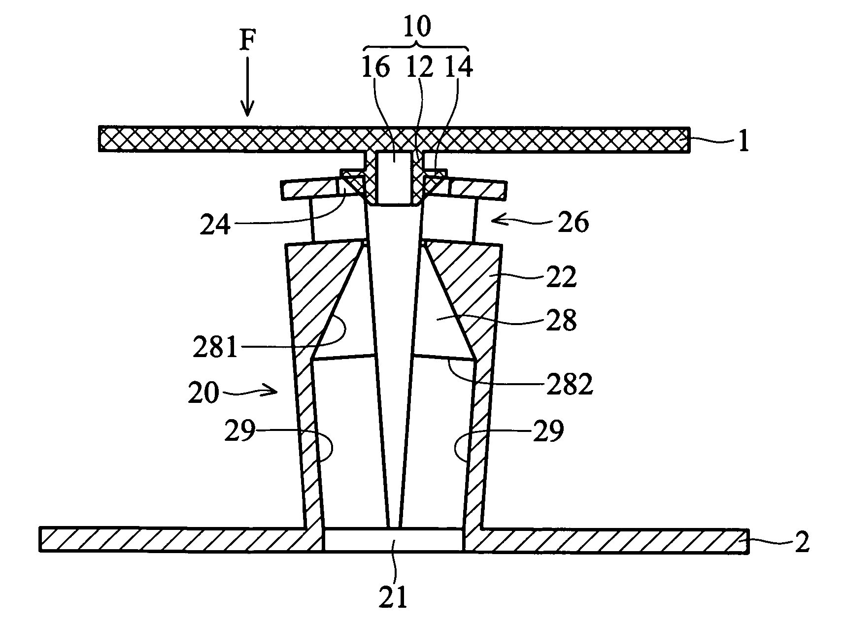
[0011] The present invention also provides an apparatus comprising a first piece, second piece and the connecting mechanism described. The hook member is integrally formed on the first piece, and the cantilevered arms of the extendable receptacle member on the second piece around the first opening. When combining the first and second pieces, the hook member is simply pressed into the holding member, the head portion thereof fixed by the holding portions of the cantilevered arm cantilevered arms. Furthermore, when a means is inserted into the tapered cavity through the first opening of the second piece, compressing the ramp surfaces of the cantilevered arms, the cantilevered arm cantilevered arms are easily separated, releasing the head portion of the hook member.

Problems solved by technology

This connecting mechanism, however, increases the number of elements required labor, thus increasing fabrication time and cost.

Method used


Image

  • Connecting mechanism and apparatus using the same
  • Connecting mechanism and apparatus using the same
  • Connecting mechanism and apparatus using the same

Examples


Embodiment Construction

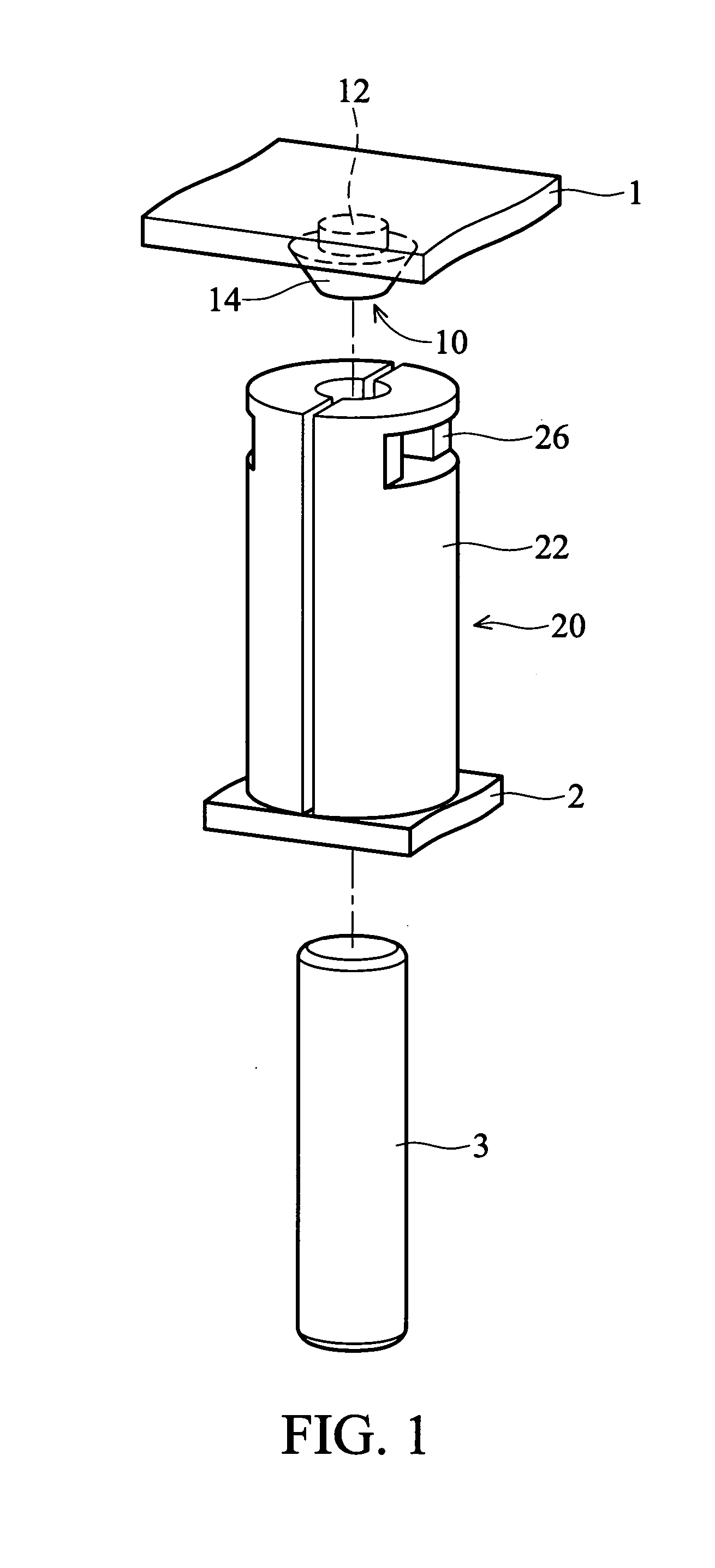
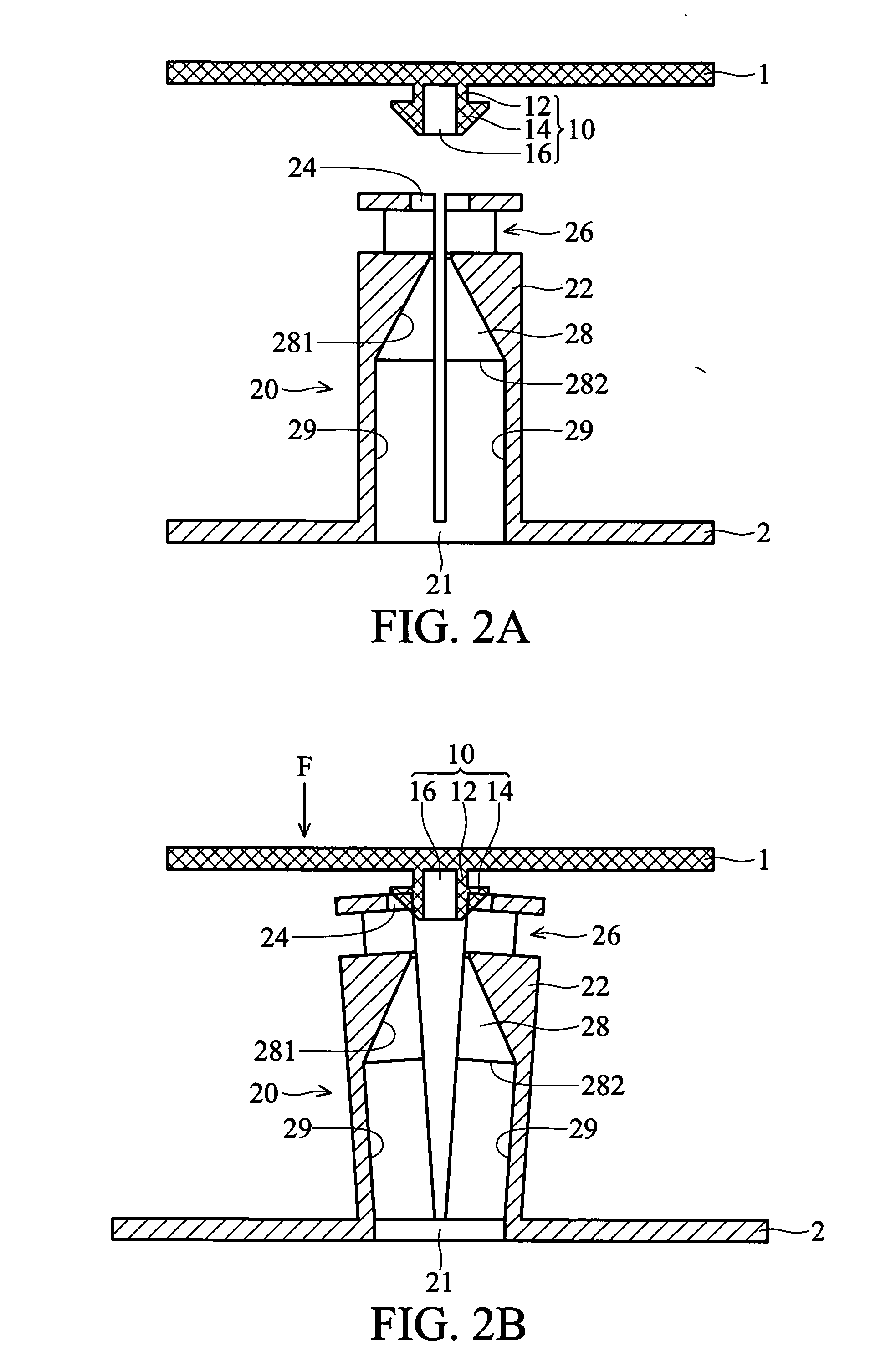
[0018]FIG. 1 is an exploded view of the connecting mechanism of the invention. FIG. 2A is a cross section thereof. In FIGS. 1 and 2A, a first and second pieces 1, 2 comprises easily-assembled connecting mechanisms 10, 20 respectively. The connecting mechanism comprises a hook member 10 and a extendable receptacle member 20. The hook member 10 includes a head portion 14 and a lever portion 12 connected to the first piece 1. The width of the head portion 14 exceeds that of the lever portion 12. In this embodiment, the head portion 14 of the hook member 10 is conical and has a recess 16 passing through the head and lever portion 14, 12, preventing shrinking of the hook member 10 during injection molding.

[0019] The extendable receptacle member 20 is integrally formed on the second piece 2, of ABS, PC or other plastic material, by injection molding. In this embodiment, the extendable receptacle member 20 is substantially cylindrical and comprises two semi-cylindrical cantilevered arm ca...


PUM


Abstract

An easily-assembled connecting mechanism and the apparatus using the same. The apparatus comprises a first and second pieces. The connecting mechanism includes a hook member and a holding member. The hook member has a head portion and a lever portion connected to the first piece; The extendable receptacle member has a plurality of cantilevered arms disposed around a through hole of the second piece. Each cantilevered arm of the extendable receptacle member has a holding portion to fix the head portion of the hook member and an inner tapered surface forming a cone. During joining of the first and second pieces, the cantilevered arms are elastically deformed, and the head of the hook member is pushed into and fixed by the holding portion of the holding member.

Description

BACKGROUND OF THE INVENTION [0001] 1. Field of the Invention [0002] The present invention relates to a connecting mechanism, and in particular to a connecting mechanism not suing screws. [0003] 2. Description of the Related Art [0004] Conventional assembly often presets screw holes or seats into which screws are mounted. This connecting mechanism, however, increases the number of elements required labor, thus increasing fabrication time and cost. SUMMARY OF THE INVENTION [0005] Accordingly, an object of the invention is to provide a connecting mechanism combining two work pieces without use of screws, thus reducing costs. [0006] Another object of the invention is to provide a connecting mechanism to simplify assembly steps and shorten fabrication time. [0007] A third object of the invention is to provide a connecting mechanism without use of screws, such that a product with the connecting mechanism of the invention can be more easily assembled automatically. [0008] The present inven...

Claims


Application Information

Patent Timeline
IPC IPC(8): F16B17/00F16B21/07H01R11/22
CPCF16B21/071Y10T403/606F16B21/073
Inventor CHEN, YI-JEN
Owner ASUSTEK COMPUTER INC
Learn More