
High-flow sediment-free fish ladder

Inactive Publication Date: 2005-04-07
TUCKER RANDALL L
View PDF7 Cites 9 Cited by
  • Summary
  • Abstract
  • Description
  • Claims
  • Application Information

AI Technical Summary

Benefits of technology

[0008] In accordance with the present invention, a new and improved fish ladder is provided which avoids or minimizes the problems and difficulties encountered in connection with conventional fish ladders of the foregoing nature, while promoting and maintaining a desired simplicity of structure and economy of manufacture.
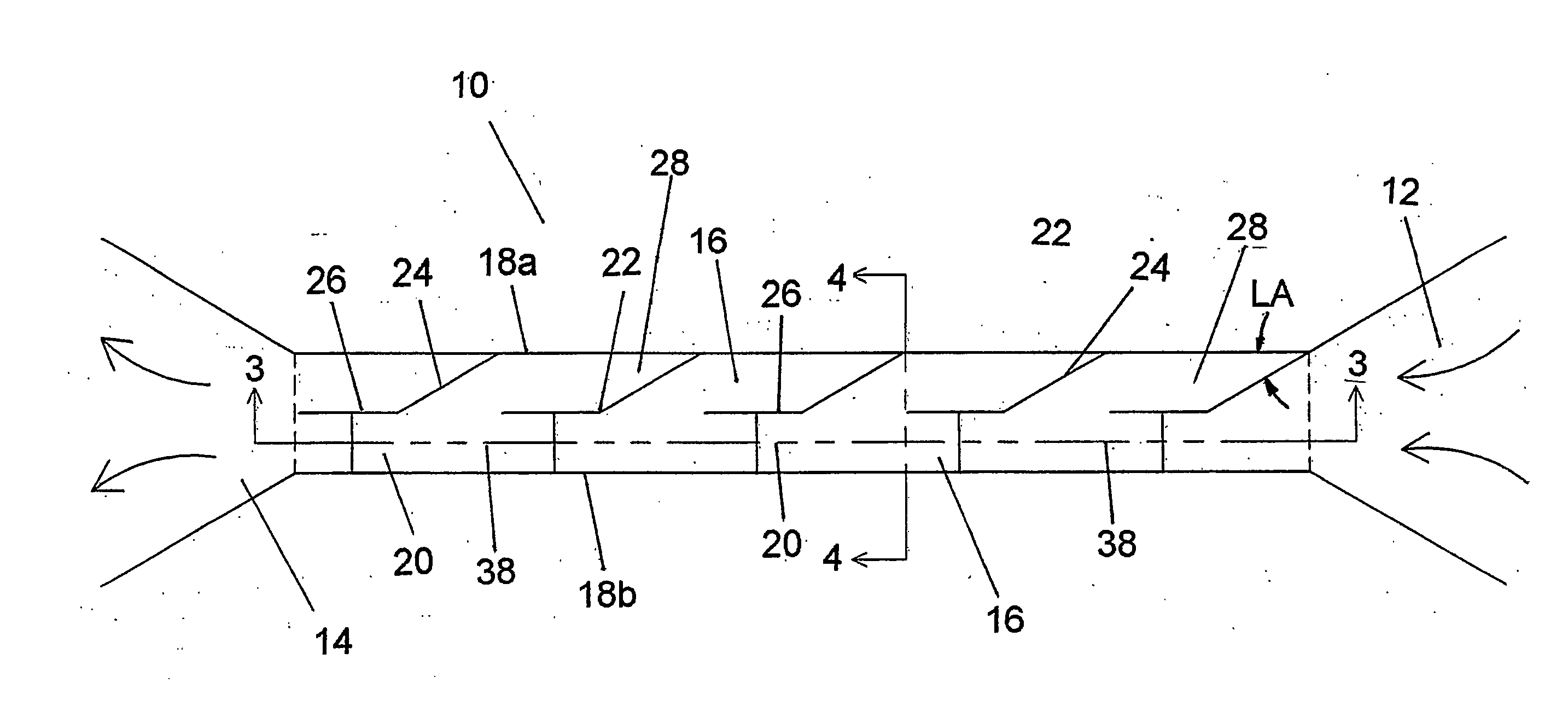
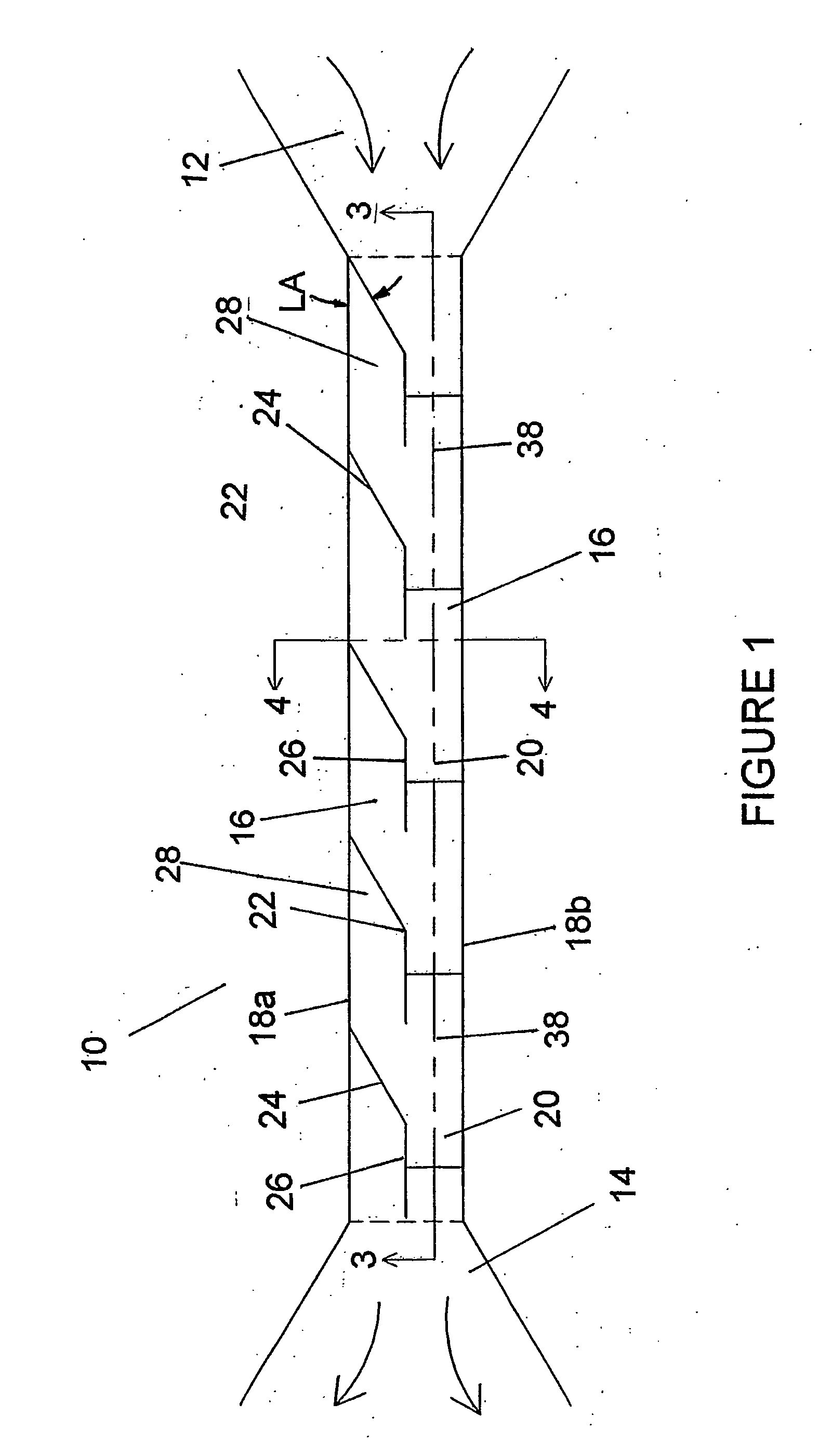
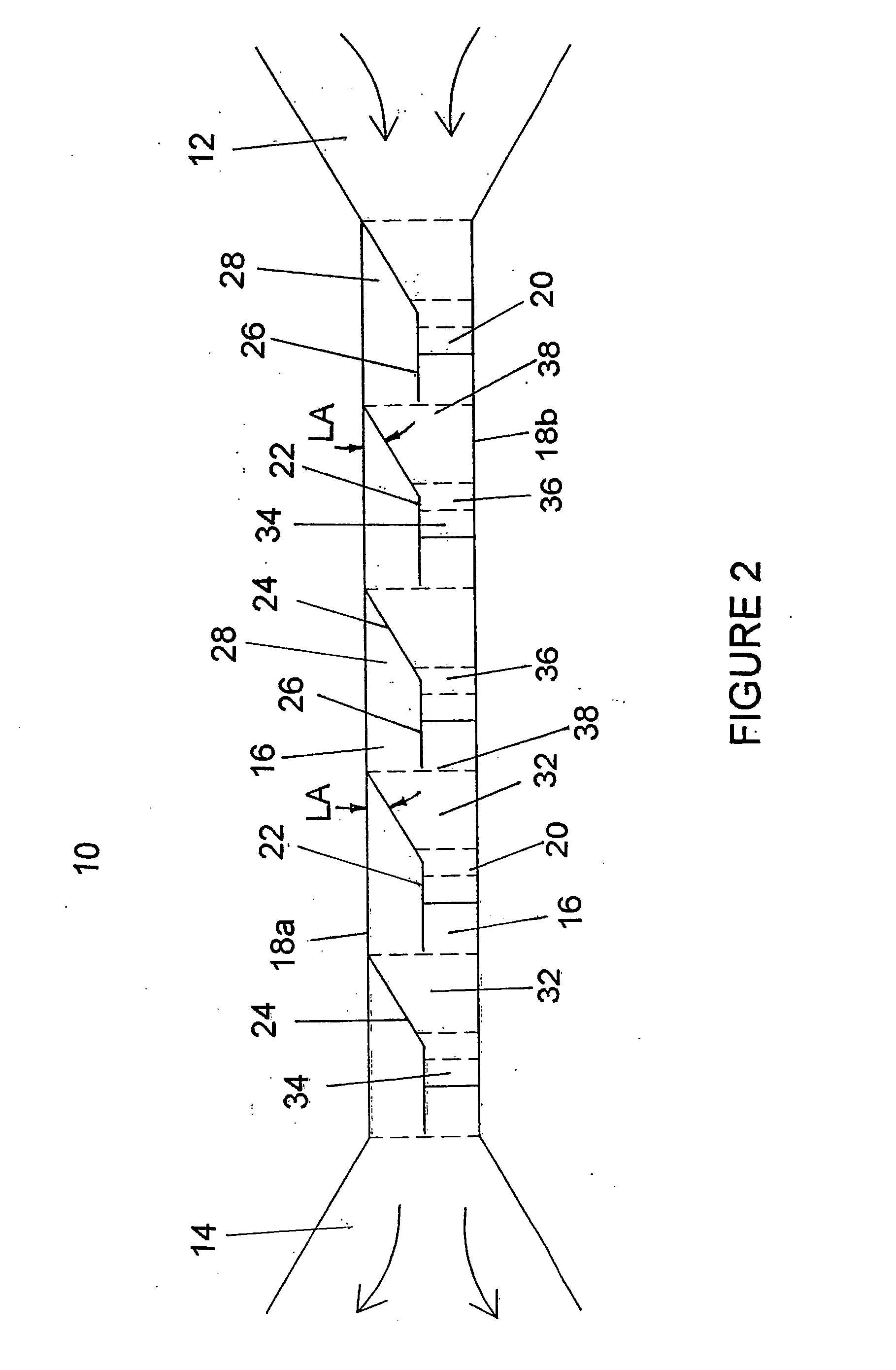
[0011] Water from the inlet flows down the fish ladder along the flow side thereof. The water is maintained on the flow side by the series of baffles that divert the flowing water toward the flow side. The water flows along the ramp portion of a stair-step and over the dam portion thereof, forming a pool against the ramp portion of the next stair-step. The water in forming or entering a pool also flows into the sheltered area behind the baffle that is adjacent the upstream stair-step across which the water has just flowed. This provides a resting area for the fish that is protected by the baffle. As such, the flow side of the fish ladder can carry a significantly increased amount of water, with respect to existing fish ladders as previously discussed, while maintaining the sheltered areas in suitable condition in which the fish may rest. Furthermore, the sheltered area protects the fish from being washed downstream, even in relatively high water conditions.
[0012] Using a series of stair-steps along the flow side of the fish ladder, in accordance with the present invention, rather than a series of cascading pools as in known apparatuses, allows the water flowing through the fish ladder to move at an increased rate without disrupting the sheltered areas. As such, a higher flow rate of water is moved through the fish ladder making it more naturally attractive to the fish, and thereby increasing the likelihood that the fish will use the structure for migration. Furthermore, the high flow rate of water along the flow side does not permit sediment to settle in the pools. Additionally, the passage in each of the baffles creates a current in the water that flows through the sheltered areas which minimizes the sediment deposits in that area as well. As such, the maintenance of the structure is significantly reduced, particularly the removal of sediment deposits.
[0014] Accordingly, the present invention provides a fish ladder capable of carrying a high flow rate of water such that fish are naturally attracted to the structure, but which also provides sheltered areas in which the fish can rest without a reduction in flow rate.
[0015] A fish ladder of the foregoing character minimizes or eliminates sedimentary deposits along the fish ladder thereby reducing or minimizing maintenance and repair of the structure without reducing the high flow rate of water or interfering with the sheltered areas in which fish can rest.
[0016] Furthermore, a fish ladder of the foregoing character also provides sheltered areas in which fish can rest out of the current of the high flow rate of water moving along the ladder.

Problems solved by technology

However, such apparatuses also have a number of disadvantages and shortcomings that render them less attractive to fish and expensive to maintain.
One such disadvantage is that the boxes retain a considerable amount of sediment due to the nature of the flow of water into and out of each box.
It will be appreciated that the buildup of sediment in the box is a significant disadvantage because a box that is filled with sediment may only provide a very shallow pool for the fish or, at times, no pool at all.
Furthermore, during high water conditions, for example in the spring or after significant rainfall, the water carries a large amount of sediment that settles in and fills the boxes.
This is, of course, detrimental to the fish migrating along the waterway that would use the fish ladder.
As such, workers spend many thousands of hours each year removing sediment from the boxes of the fish ladders.
As such, the fish may not be attracted to the water flowing through the conventional fish ladder resulting in reduced use of the ladder by migrating fish.
Rather, the water rushes along the fish ladder creating turbulence and water currents flowing in the pools reducing the area in which the fish can rest and often times washing the fish back down the ladder to the lower level of the outlet.
Another disadvantage of existing fish ladders is the area that is commonly required to construct a conventional fish ladder formed of cascading boxes.
However, in other situations where a fish ladder would otherwise be desirable, the construction thereof is not possible due to space or access limitations, such as through a culvert running beneath a roadway, for example.

Method used


Image

  • High-flow sediment-free fish ladder
  • High-flow sediment-free fish ladder
  • High-flow sediment-free fish ladder

Examples


Embodiment Construction

[0023] Referring now in greater detail to the drawings, wherein the showings are for the purpose of illustrating preferred embodiments of the invention only, and not for the purpose of limiting the invention, FIG. 1 illustrates a fish ladder 10 extending between a flow inlet 12 and a flow outlet 14. The fish ladder has a bottom wall 16 from which a pair of spaced-apart sidewalls 18a and 18b upwardly extend. A series of projections or stair-steps 20 extend from bottom wall 16, and are longitudinally spaced apart along ladder 10. A series of baffles 22 also project from bottom wall 16, and are likewise longitudinally spaced apart along ladder 10. Each baffle 22 is generally speaking, laterally adjacent a stair-step 20, and has a diverter portion 24 and a divider portion 26. Diverter portion 24 extends from sidewall 18a in the downstream direction at an angle toward sidewall 18b, terminating or merging in the preferred arrangement at divider portion 26. The divider portion extends gene...


PUM


Abstract

A fishladder (10) for use along a waterway includes a channel having a bottom wall (16), a pair of opposing, up-wardly extending sidewalls (18a, b) and opposing open ends. A series of projections (20) are disposed along the channel between the opposing walls (18a, b), and a series of baffles (22) are also disposed along the channel adjacent the series of projections. The baffles (22) define a sheltered side (28), having sheltered areas with a low water flow rate in which fish can rest, and a flow side capable of carrying water having a higher water flow rate and along which fish can advance up the fish ladder. A passage (30) extends through the battles, which allows water to flow through the sheltered areas at a rate capable of preventing the build-up of sediment in teh same sheltered areas, but which does not significantly impede the ability of fish to rest in these areas.

Description

[0001] This application claims the priority benefit of U.S. provisional patent application Ser. No. 60 / 322,697, filed Sep. 12, 2001. [0002] This invention relates to the art of fish ladders and, more particularly, to fish ladders having an improved flow rate to facilitate usage while minimizing the retention of sediment.BACKGROUND OF THE INVENTION [0003] Fish ladders have been provided heretofore and generally are comprised of a series of boxes positioned adjacent one another in an incrementally elevated fashion, in a stepped or ladder configuration that allows fish to migrate from one box to an upstream box. The series of boxes includes a flow inlet above an obstruction, e.g., waterfall or dam, in a waterway and a flow outlet below the obstruction. Typically the inlet is elevated from the level of the outlet so that water from the waterway will flow through the fish ladder from the inlet to the outlet. In this manner, water will flow into the uppermost box of the fish ladder, then ...

Claims


Application Information

Patent Timeline
IPC IPC(8): E02B8/08
CPCE02B8/085Y02A40/60
Inventor TUCKER, RANDALL L
Owner TUCKER RANDALL L
Learn More