Fluid line connector assembly with antimicrobial coating

a technology of fluid line connectors and connector assemblies, which is applied in the direction of hose connections, pipe joints, couplings, etc., can solve the problems of metal sealing formation, assembly becomes fluid tight, undesirable changes in observable characteristics, etc., to avoid or minimize problems and difficulties encountered, increase performance and reliability, and reduce the effect of assembly siz

Inactive Publication Date: 2007-06-14
DORMONT MFG
View PDF19 Cites 2 Cited by
  • Summary
  • Abstract
  • Description
  • Claims
  • Application Information

AI Technical Summary

Benefits of technology

[0008] In accordance with the present invention, a thin-walled, flexible- fluid line connector assembly is provided that avoids or minimizes the problems and difficulties encountered in connection with connector assemblies of the foregoing nature, while promoting an increase in performance and reliability and maintaining a desired simplicity of structure, economy of manufacture, as well as ease of installation and maintenance.

Problems solved by technology

This displacement causes the flare portion of the tubing to be compressively engaged between the flare fitting and flare nut, and causes a metal-to-metal seal to form between the tubing, the flare fitting and the flare nut such that the assembly becomes fluid tight.
A disadvantage of connector assemblies having a flexible coating layer is that the conditions giving rise to the need for regular sanitization of the fluid line connector assembly also promote the growth of microorganisms, such as fungi, bacteria, mold and mildew.
These microorganisms attack the flexible coating layer often causing undesirable changes in the observable characteristics of the connector assembly, such as discoloration, tackiness and even foul odor.
Furthermore, the deterioration of physical and mechanical properties of the coating layer and a corresponding overall reduction in product life often result from the continued re-growth of these microorganisms.
Such chemical agents may also contribute to the degradation of the appearance of the connector assembly, as well as the deterioration of the physical and mechanical properties of the flexible coating layer.
As a result, the repeated exposure to these chemical agents contributes to an overall reduction in the life of the connector assembly.

Method used


Image

  • Fluid line connector assembly with antimicrobial coating
  • Fluid line connector assembly with antimicrobial coating
  • Fluid line connector assembly with antimicrobial coating

Examples


Embodiment Construction

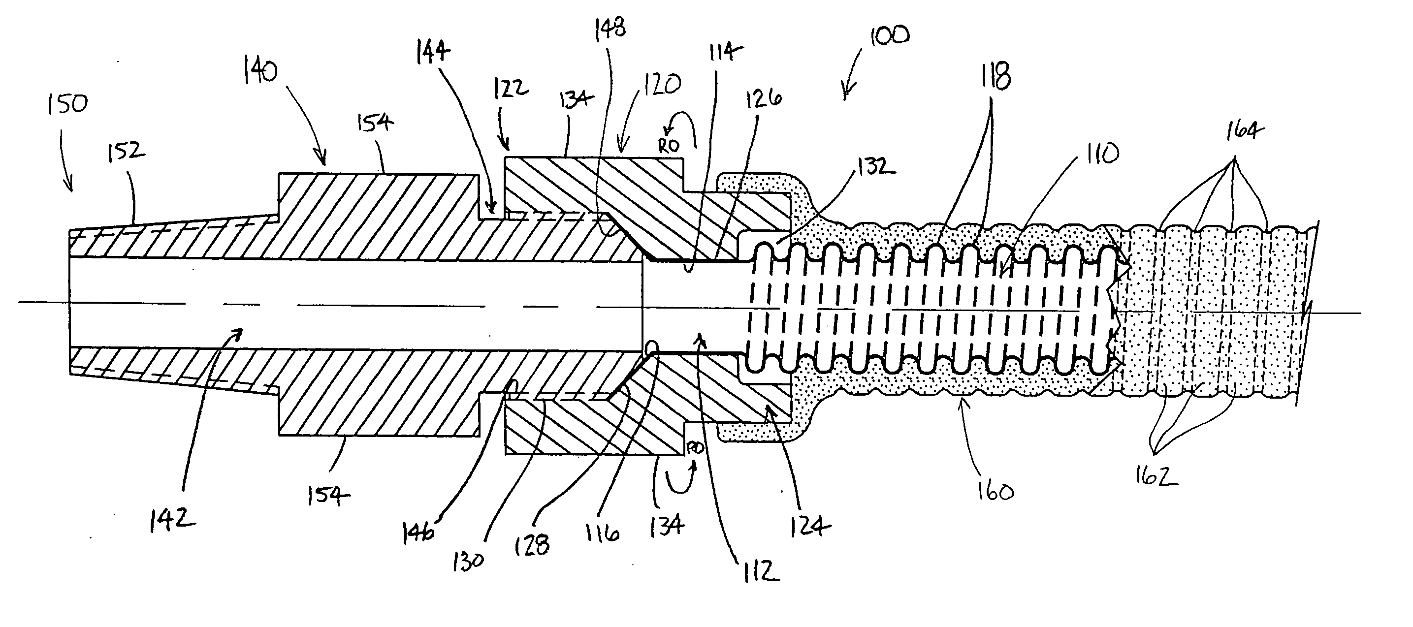
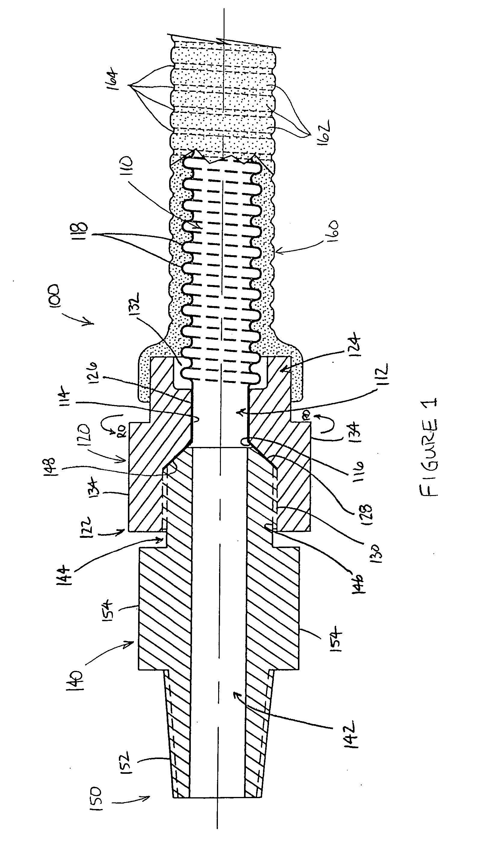
[0013] Referring now in greater detail to FIG. 1, wherein the showings are for the purposes of illustrating preferred embodiments of the invention only and not for the purpose of limiting the invention, FIG. 1 illustrates a fluid line connector assembly 100 that includes a length of thin-walled flexible tubing 110 having a plurality of helical corrugations 118 extending between opposing tubing ends 112, a flare nut 120 supported on at least one of the tubing ends, a flare fitting 140 cooperable with the flare nut, and a flexible coating layer 160 extending between the opposing ends. It will be appreciate that only one end of fluid line connector assembly 100 is shown in FIG. 1.

[0014] Tubing end 112 includes a cylindrical journal portion 114 and a flare portion 116. Flare nut 120 includes a journal passage 126 cooperable with journal portion 114, such that the flare nut is receivingly engaged upon tubing end 112. Flare nut 120 includes a threaded end 122 and a recess end 124 having ...


PUM


Abstract

A fluid line connector assembly including a length of flexible tubing having opposing tubing ends, and an end fitting rotatably supported on one of the tubing ends. A flexible coating extends along the exterior of the length of tubing. The coating is formed from a polymeric material that includes a biocide agent dispersed therein for killing and retarding the growth of microorganisms. The connector assembly can optionally include a braided sheath extending along the exterior of the length of tubing. In such case, the flexible coating extends along the exterior of the braided sheath.

Description

BACKGROUND OF THE INVENTION [0001] This invention relates to the art of fluid line connector assemblies and, more particularly, to thin-walled, flexible fluid line connector assemblies for use in low-pressure applications, such as for connecting between a gas supply line and a stationary or movable gas appliance, a commercial fryer, for example. [0002] Thin-walled, flexible fluid line connector assemblies have been provided heretofore and generally include a length of thin-walled, corrugated, flexible tubing having opposing non-corrugated tubing ends and a fluid-tight fitting arrangement on at least one of the tubing ends. Known connector assemblies commonly include a fitting arrangement on each tubing end. These fitting arrangements commonly include threaded connectors, quick-connect fittings and / or multi-plane swivel fittings, either alone or in any one of numerous combinations. [0003] For example, one such known connector assembly includes a flare nut retained on each tubing end ...

Claims


Application Information

Patent Timeline
Patent Type & Authority Applications(United States)
IPC IPC(8): F16L25/00F16L33/01
CPCF16L33/01F16L2201/44
Inventor SEGAL, EVANJ
Owner DORMONT MFG
Why Eureka
Try Eureka