Apparatus at a draw frame for supplying fibre slivers to a drawing mechanism comprising at least two pairs of rollers

a technology of drawing mechanism and draw frame, which is applied in the direction of drafting machines, spinning machines, textiles and paper, etc., can solve the problems of affecting the uniform transfer of slivers, affecting the measurement of slivers, and affecting the uniformity of slivers

Inactive Publication Date: 2005-04-14
TRUETZSCHLER GMBH & CO KG
View PDF7 Cites 36 Cited by
  • Summary
  • Abstract
  • Description
  • Claims
  • Application Information

AI Technical Summary

Benefits of technology

[0012] As a result of the sliver-guiding device according to the invention, the fibre slivers are held down at a location in which they are still oriented substantially in a plane, that is to say in which the slivers arranged to the outside have not yet been folded over upon themselves and over slivers arranged further to the inside. As a result it is ensured that the group of fibre slivers has a level orientation, which is important for entry into the nip of the pair of take-in rollers of the drawing mechanism. When a measuring element for determining thickness variations either in the fibre sliver group consisting of several slivers or for individual sliver measurement is provided between the feed table and the drawing mechanism, measuring the fibre slivers next to one another in a plane is highly advantageous. It is also advantageous for the apparatus according to the invention to be provided upstream of the drawing mechanism, upstream of the measuring element and / or upstream of a guide element directing the fibre slivers laterally.

Problems solved by technology

The fibre slivers are displaced upwards so that—in a side view—they are at different heights from one another, which can impair uniform transfer of the slivers and, especially, their horizontal orientation.
Where the guide element includes, or is in the form of, a sliver thickness measuring element, sliver measurement can be impaired by the slivers' being folded over one another.

Method used


Image

  • Apparatus at a draw frame for supplying fibre slivers to a drawing mechanism comprising at least two pairs of rollers
  • Apparatus at a draw frame for supplying fibre slivers to a drawing mechanism comprising at least two pairs of rollers
  • Apparatus at a draw frame for supplying fibre slivers to a drawing mechanism comprising at least two pairs of rollers

Examples


Embodiment Construction

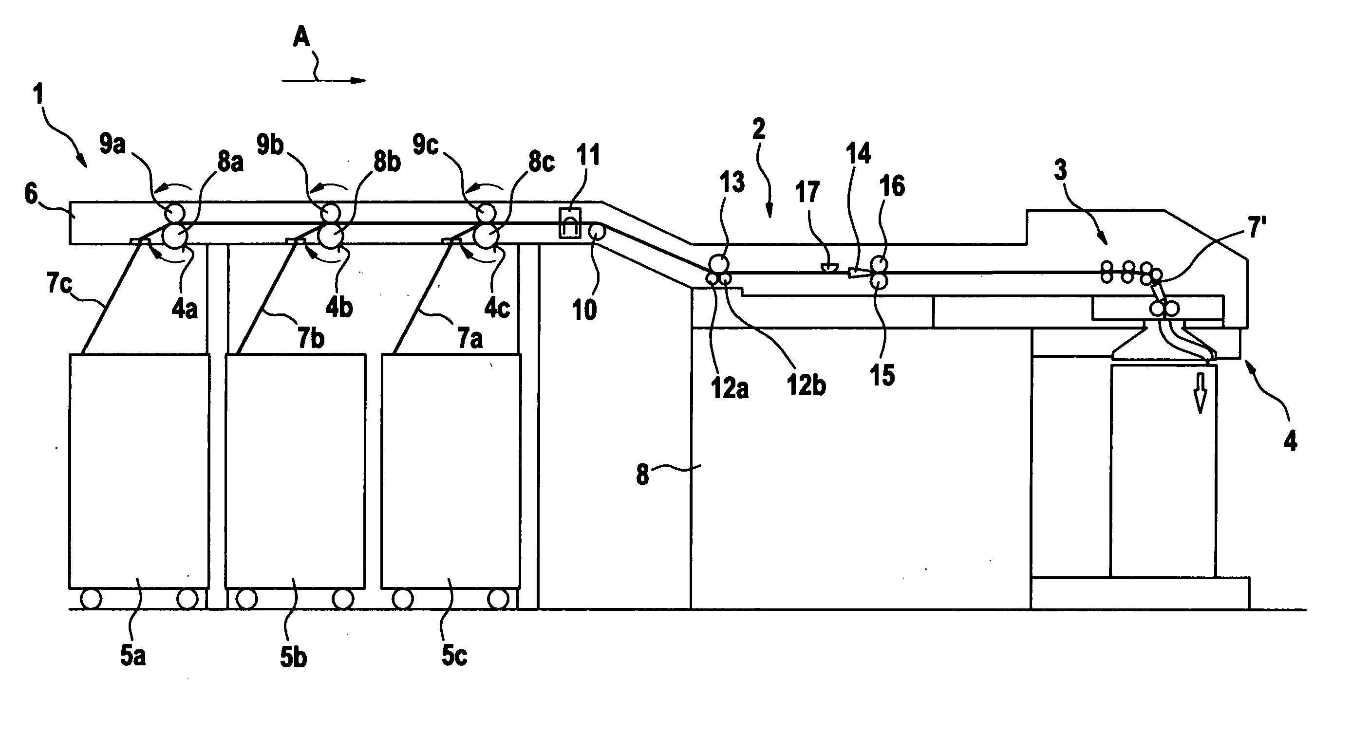
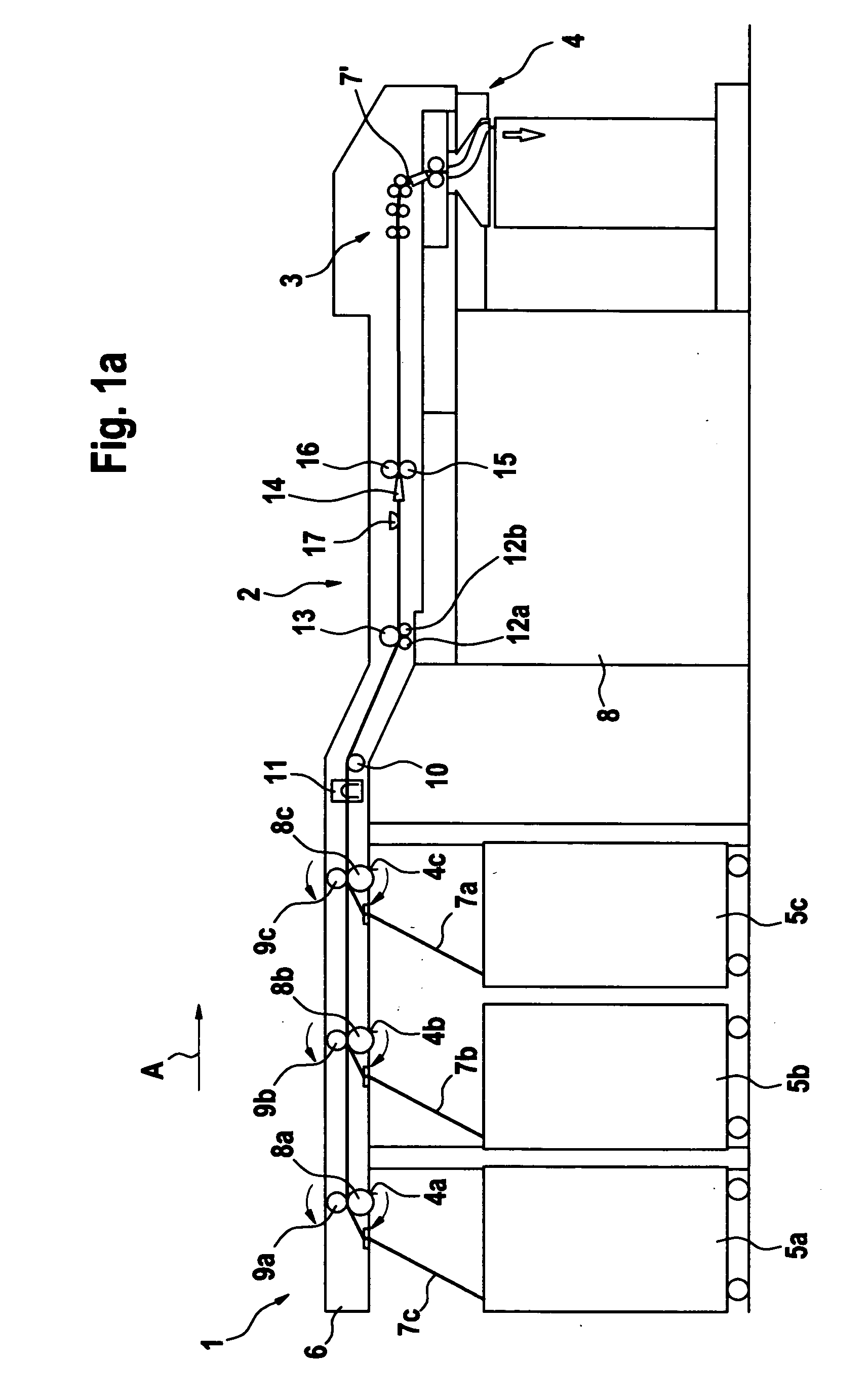
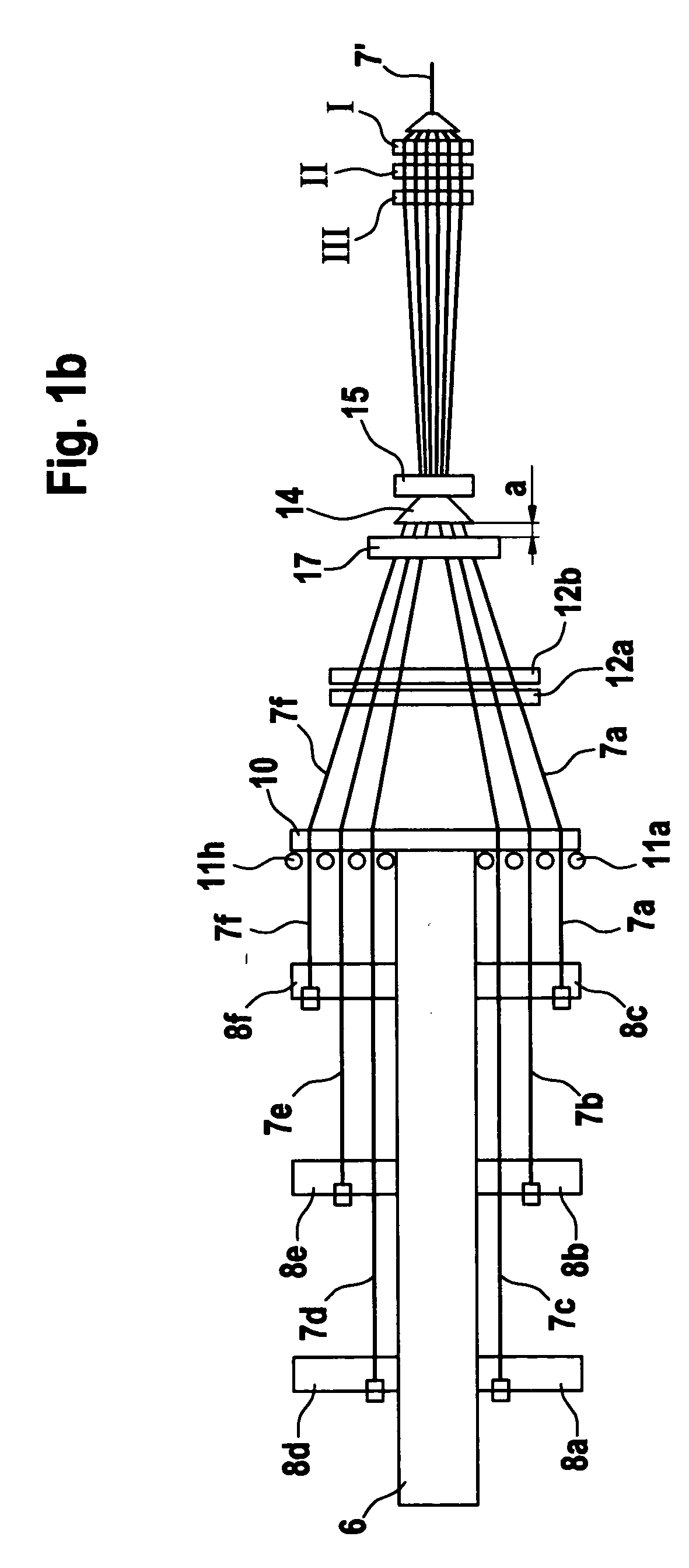
[0027] With reference to FIG. 1a, a draw frame, for example a TD 03 draw frame made by Trützschler GmbH & Co. KG of Mönchengladbach, Germany, has a feed region 1, a measurement region 2, a drawing mechanism 3 and a sliver coiling arrangement 4. In the feed region 1, spinning cans 5a to 5c (circular cans) of a draw frame are arranged below the sliver feed table 6 (creel) in two rows of cans (see FIG. 1b), each row having three cans in the embodiment shown; the feed slivers 7a to 7f are drawn off by means of supply rollers 8a to 8f and supplied to the drawing mechanism 3. With each driven supply roller 8a to 8f there is associated a top roller 9a to 9f (only 9a to 9c can be seen in the drawings), which rotates together with the supply roller. Located in the region of the feed table are six roller pairs 8, 9 (cf. FIG. 1b), each consisting of a top roller and a supply roller. Fibre slivers 7a to 7f are lifted out of the spinning cans 5a to 5f and guided on the feed table 6 towards the d...


PUM

PropertyMeasurementUnit
obtuse angleaaaaaaaaaa
heightaaaaaaaaaa
lengthaaaaaaaaaa

Abstract

A draw frame has a drawing mechanism comprising at least two pairs of rollers to which the fibre slivers are fed by a plurality of supply rollers mounted on a feed table. The fibre slivers—seen in a top view—run next to one another and towards one another laterally, and a guide element is provided between a feed table and the drawing mechanism, the lateral faces of which guide element are capable of directing the incoming fibre slivers laterally. In order to allow uniform transfer of the slivers and to enable the slivers to be oriented substantially in a plane, a sliver-guiding device is arranged across the width upstream of the guide element at a spacing therefrom at which the fibre slivers are arranged substantially in a plane, the fibre slivers passing through underneath and in contact with the sliver-guiding device.

Description

CROSS REFERENCE TO RELATED APPLICATION [0001] This application claims priority from German Patent Application No. 103 47 811.6 filed Oct. 10, 2003, the entire disclosure of which is incorporated herein by reference. BACKGROUND OF THE INVENTION [0002] The invention relates to an apparatus at a draw frame for supplying fibre slivers to a drawing mechanism comprising at least two pairs of rollers. [0003] In a known form of draw frame, the fibre slivers are fed to the drawing mechanism by a plurality of supply rollers mounted on a feed table, the fibre slivers—seen in a top view—running next to one another and towards one another laterally, and a guide element being provided between the feed table and the drawing mechanism, the lateral faces of which guide element are capable of directing the incoming fibre slivers laterally. In a known apparatus, the guide element has two lateral faces which taper in towards one another, as a result of which the fibre slivers are guided laterally. In t...

Claims


Application Information

Patent Timeline
Patent Type & Authority Applications(United States)
IPC IPC(8): D01H5/00D01H5/72D01H5/18D01H5/22D01H13/04D01H13/26
CPCD01H13/04D01H5/005
Inventor TEMBURG, JOSEF
Owner TRUETZSCHLER GMBH & CO KG
Why Eureka
Try Eureka