Unlock instant, AI-driven research and patent intelligence for your innovation.
Two-position quick-change saw
What is Al technical title?
Al technical title is built by PatSnap Al team. It summarizes the technical point description of the patent document.
a two-position, quick-change technology, applied in the direction of metal sawing equipment, sawing equipment, metal-working equipment, etc., can solve the problems of preventing cutting accuracy, affecting cutting accuracy, and affecting cutting accuracy,
Inactive Publication Date: 2005-04-14
ERISOTY GREGORY J +1
View PDF13 Cites 0 Cited by
Summary
Abstract
Description
Claims
Application Information
AI Technical Summary
This helps you quickly interpret patents by identifying the three key elements:
Problems solved by technology
Method used
Benefits of technology
Benefits of technology
"The present invention provides a saw frame assembly that allows for easy tensioning and release of the mounted blade, as well as conversion between two configurations. The assembly includes a frame with a back member, handle structure, and a single elongate arm member. The arm member is mounted on the back member and can be moved between a first position and a second position. The assembly also includes blade-engaging elements on the frame that can orient the mounted blade either parallel or at an angle to the frame. The blade-engaging elements are constructed to engage one end of a removably mounted saw blade. The assembly is comfortable and convenient to use and operate. It can be easily converted between the two configurations and is practical and economical to manufacture."
Problems solved by technology
The saw provided by Duffy would however appear to suffer from several significant drawbacks.
First of all, because a plurality of laterally stacked fingers are employed the limited space available requires each finger to be relatively thin and, therefore, to be relatively weak.
Moreover, because the fingers are spaced in different lateral planes the mounted blade must (at least when either of two of the three fingers are used) extend at an angle to the medial plane; albeit relatively small, such angular displacement would preclude accuracy of cutting (unless the saw itself were held at an artificial angle to the workpiece).
Finally, because forward blade-engagement elements are provided only on the fingers of the Duffy saw, the blade must be displaced from the back member in all configurations, and minimal spacing capability cannot therefore be achieved.
Method used
Image
Click on the blue label to locate the original text in one second.
Reading with bidirectional positioning of images and text.
Examples
Embodiment Construction
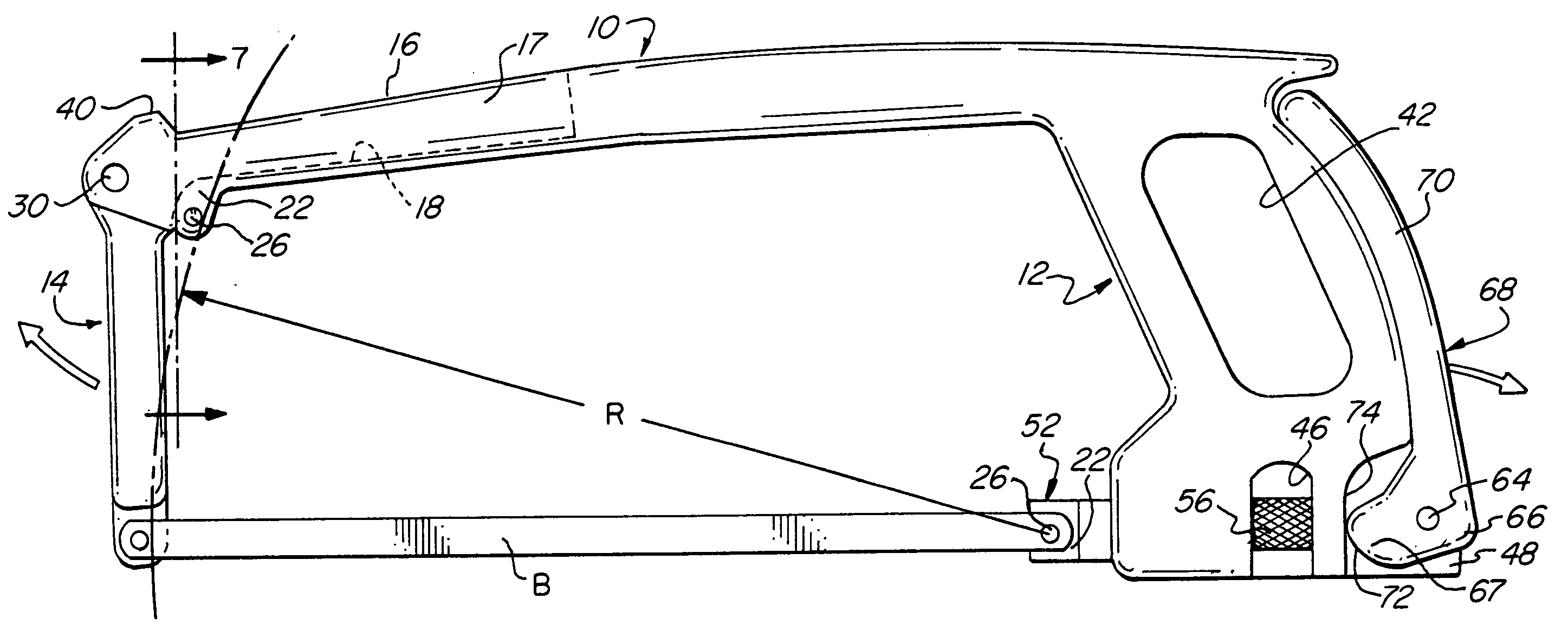
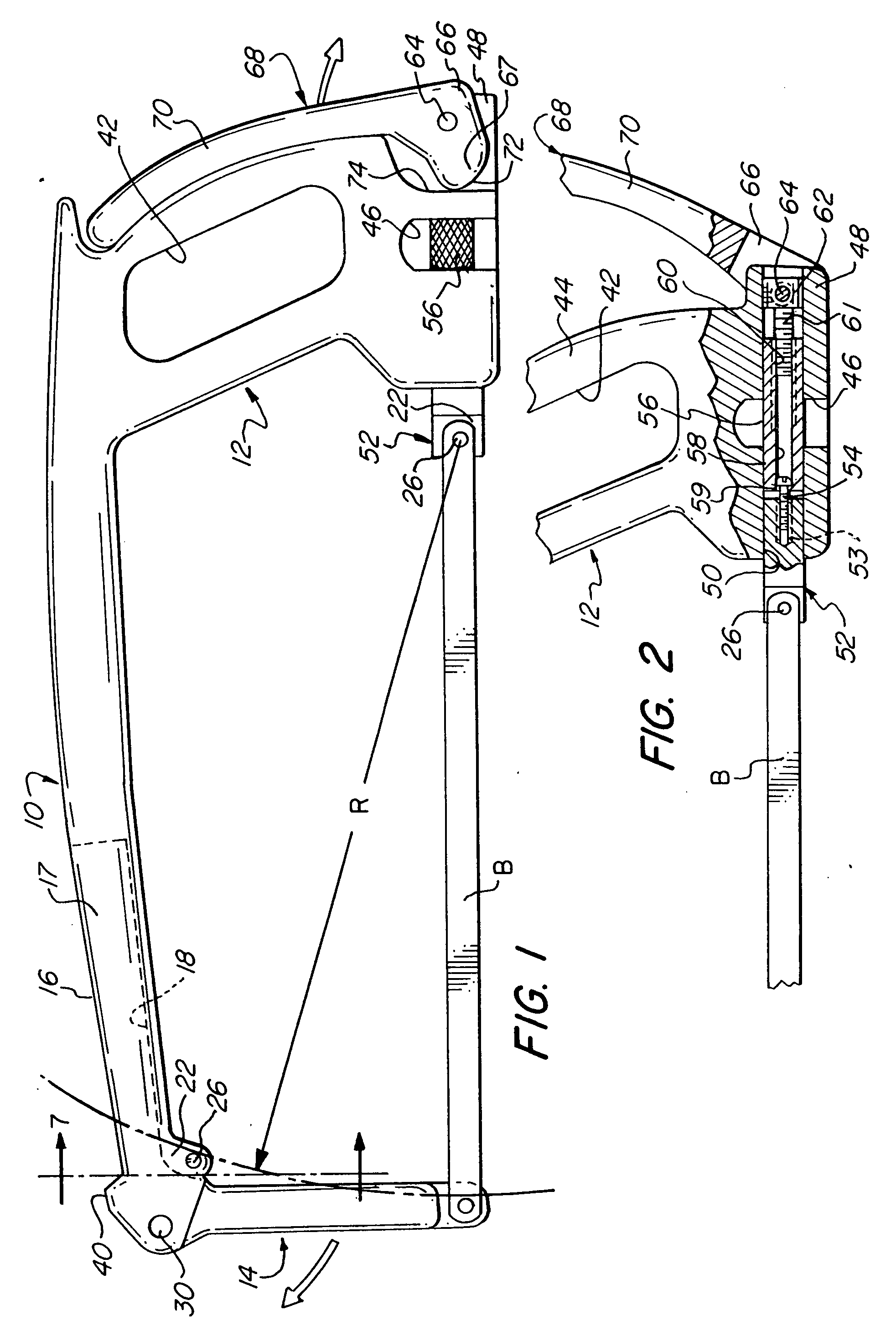
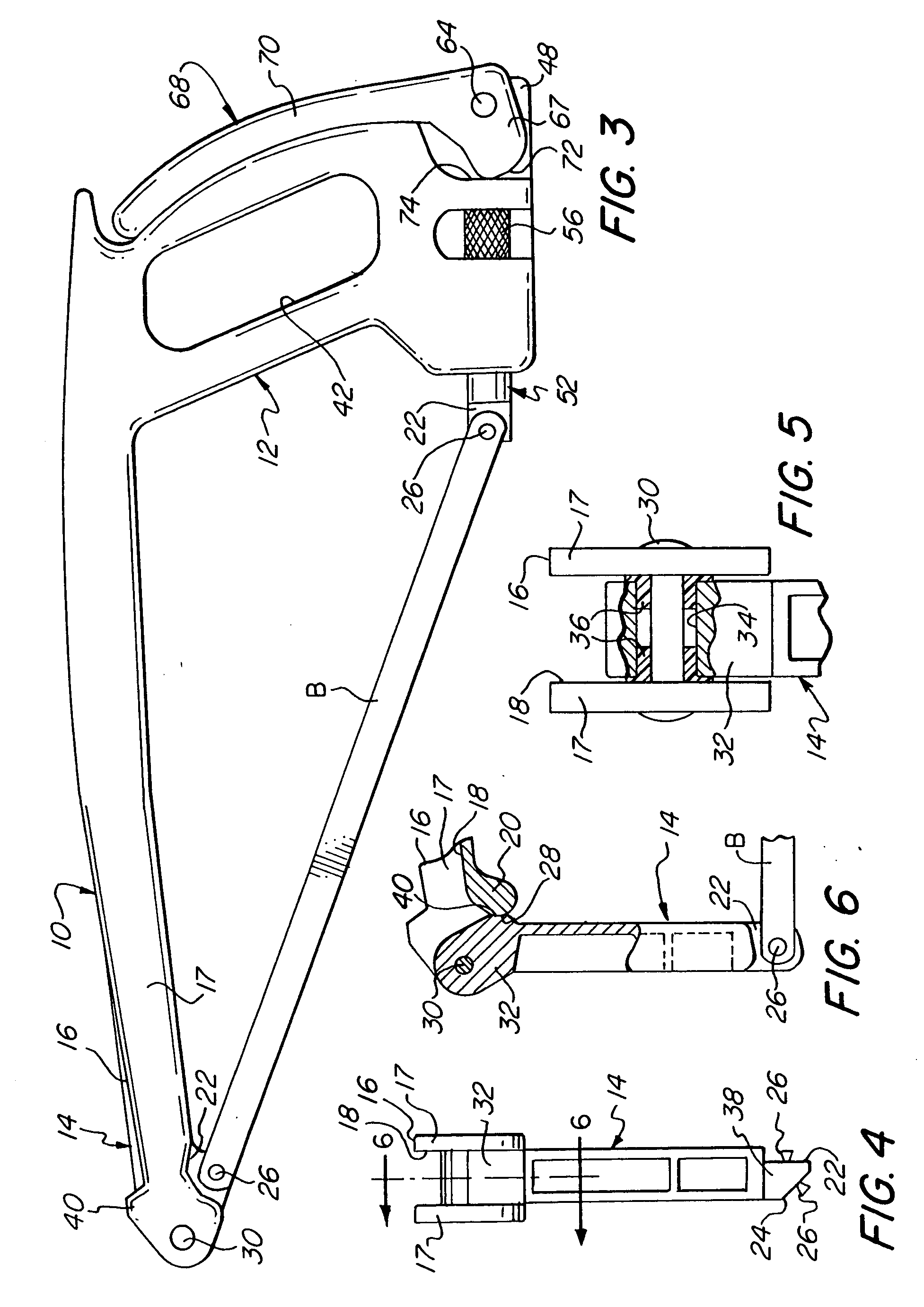
[0022] Turning now in detail to the appended drawings, therein illustrated is a hacksaw embodying the present invention and consisting of a frame comprised of a back member, generally designated by the numeral 10, handle structure generally designated by the numeral 12, and a swing arm generally designated by the numeral 14. The forward portion 16 of the back member 10 is formed with an upwardly opening channel 18, and has a downwardly projecting mounting lobe 20 with a “90°” lateral surface 22 on one side and a “45°” lateral surface 24 on its opposite side; the lobe 20 provides a forwardly directed, curved bearing surface 28, and a mounting pin 26 projects normal to each of the surfaces 22, 24.
[0023] A radial rivet 30 spans the lateral walls 17 defining the forward portion 16 of the back member 10 and extends through the passage 34 in the hub portion 32 of the swing arm 14, thus serving as an axle for rotatably mounting the swing arm 14. A pair of flanged bushings 36 (made for exa...
PUM
Property
Measurement
Unit
angle
aaaaa
aaaaa
tension
aaaaa
aaaaa
radius
aaaaa
aaaaa
Abstract
A two-position, quick-change hacksaw consists of a back member, handle structure adjacent a rearward end portion of the back member, and a swing arm adjacent the forward end. The free end of the swing arm and the forward end portion of the back member have coplanar blade-engaging elements thereon which serve to engage the forward end of the blade and which are commonly disposed on an arc that circumscribes a third coplanar blade-engaging element disposed on a coupling block of a tensioning mechanism for mounting the rearward end of the blade. Two coplanar sets of transversely paired engagement elements enable mounting of the blade both in a plane parallel to a medial plane of the frame and also in a plane disposed at a substantial angle thereto. In one configuration, with the swing arm in its inoperative position, the saw is adapted for cutting within a relatively confined space; with the swing arm in its operative position the saw is configured for cutting within a relatively unconfined space.
Description
BACKGROUND OF THE INVENTION [0001] Reconfigurable saws of various kinds are well-known in the art, as evidenced by the following United States patents: No. 1,028,230No. 2,782,821No. 1,245,345No. 4,680,863No. 2,173,365No. 5,873,170No. 2,514,880[0002] The incorporation of a pivotable arm into a hacksaw frame is disclosed in U.S. Pat. Nos. 2,309,816 and 5,471,752, and the following United States patents provide a variety of blade-tensioning arrangements: Des. 428,321No. 1,565,861No. 766,077No. 3,636,997No. 1,080,365No. 4,349,059No. 1,187,460No. 6,070,330No. 1,517,827No. 6,079,109[0003] Additional forms of saws are disclosed in the following United States patents: Des. 318,006No. 2,580,896No. 1,206,638No. 2,662,567No. 1,394,174No. 3,822,731No. 1,522,598No. 4,835,869No. 1,695,231[0004] Among the foregoing, particular note may be made of Duffy U.S. Pat. No. 4,680,863. Duffy describes a saw in which the blade can be disposed either parallel to the back member or in a number of angular r...
Claims
Application Information
Patent Timeline
Application Date:The date an application was filed.
Publication Date:The date a patent or application was officially published.
First Publication Date:The earliest publication date of a patent with the same application number.
Issue Date:Publication date of the patent grant document.
PCT Entry Date:The Entry date of PCT National Phase.
Estimated Expiry Date:The statutory expiry date of a patent right according to the Patent Law, and it is the longest term of protection that the patent right can achieve without the termination of the patent right due to other reasons(Term extension factor has been taken into account ).
Invalid Date:Actual expiry date is based on effective date or publication date of legal transaction data of invalid patent.
Patent Type & Authority Applications(United States)
IPC IPC(8): B23D49/12B23D51/03B23D51/12
CPCB23D49/12B23D51/125B23D51/03
Inventor ERISOTY, GREGORY J.MACQUEEN, RAYMOND J. JR.
