
Brake pedal assembly for vehicle

Inactive Publication Date: 2005-04-14
HYUNDAI MOTOR CO LTD
View PDF9 Cites 3 Cited by
  • Summary
  • Abstract
  • Description
  • Claims
  • Application Information

AI Technical Summary

Benefits of technology

[0004] An embodiment of the present invention provides a brake pedal assembly for a vehicle adapted to reduce injury to a driver's ankle and / or tibia when receiving impact from the brake pedal assembly during a vehicle collision.

Problems solved by technology

Typically, when a vehicle collision takes place, a dash panel and brake pedal assembly are likely to thrust toward a driver due to a deformation of the vehicle engine compartment.
The driver, forcibly depressing the brake pedal at this time typically injures his or her ankle and / or tibia.

Method used


Image

  • Brake pedal assembly for vehicle
  • Brake pedal assembly for vehicle
  • Brake pedal assembly for vehicle

Examples


Embodiment Construction

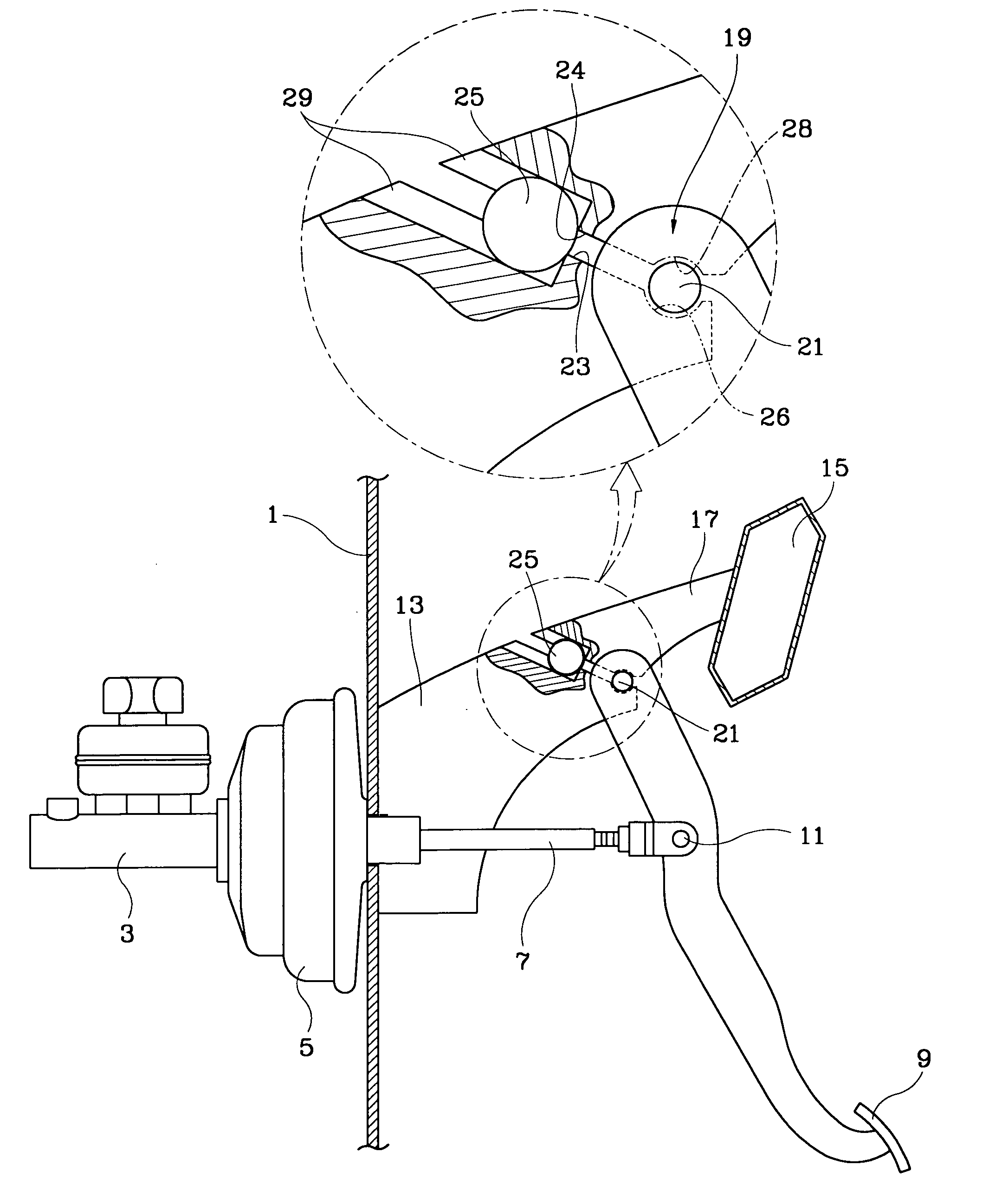
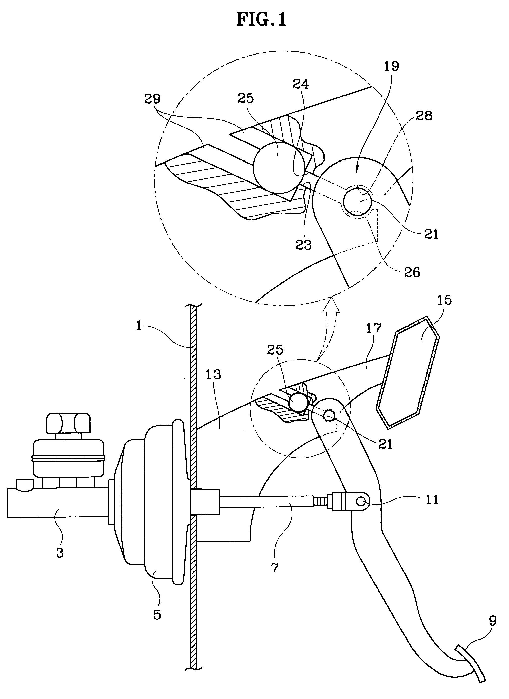
[0010] As shown in FIG. 1, a dash panel 1 is installed with a brake master cylinder 3 and a booster 5. A pushrod 7 penetrating the dash panel 1 from the booster 5 is coupled to a brake pedal 9 via a hinge 11. The brake pedal 9 is pivotally supported by a brake pedal hinge 21 and a hinge supporting part 19, which is formed between a dash bracket 13 fixed to the dash panel 1 and a cowl bracket 17 fixed to a cowl cross member 15.

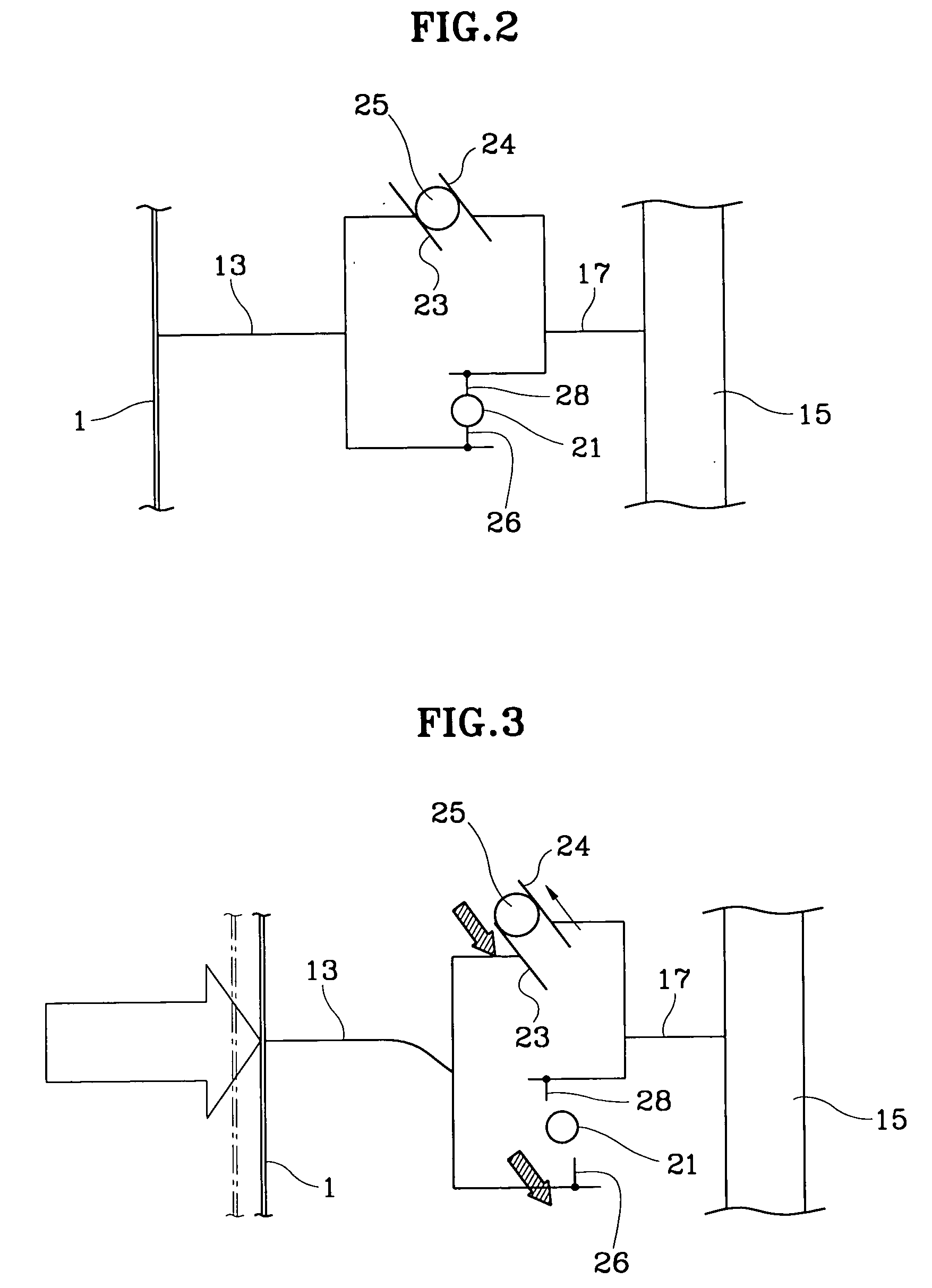
[0011] A hinge releasing means is placed between the dash bracket 13 and the cowl bracket 17 for releasing the hinge supporting part 19 from a restrictive state when the dash bracket 13 moves relatively in relation to the cowl bracket 17. The hinge releasing means includes two linear sliding sides 23, 24 and a ball 25, wherein the linear sliding sides 23 and 24 are formed to face each other between the dash bracket 13 and cowl bracket 17 and to be inclined in relation to a moving direction of the dash bracket 13 during a collision, and the ball 25 is inserted ...


PUM


Abstract

A brake pedal assembly for a vehicle is adapted to release a brake pedal from a restrictive state when a vehicle collision occurs, thereby preventing an impact from being transmitted to the driver through the dash panel and pushrod and minimizing injury to a driver's ankle and / or tibia.

Description

CROSS-REFERENCE TO RELATED APPLICATIONS [0001] This application claims priority to Korean Application No. 10-2003-0070555, filed on Oct. 10, 2003, the disclosure of which is incorporated fully herein by reference. FIELD OF THE INVENTION [0002] Generally, the present invention relates to a vehicle brake pedal assembly. More particularly, the brake pedal assembly helps prevent injury to a driver depressing the brake pedal during a collision. BACKGROUND OF THE INVENTION [0003] Typically, when a vehicle collision takes place, a dash panel and brake pedal assembly are likely to thrust toward a driver due to a deformation of the vehicle engine compartment. The driver, forcibly depressing the brake pedal at this time typically injures his or her ankle and / or tibia. SUMMARY OF THE INVENTION [0004] An embodiment of the present invention provides a brake pedal assembly for a vehicle adapted to reduce injury to a driver's ankle and / or tibia when receiving impact from the brake pedal assembly d...

Claims


Application Information

Patent Timeline
IPC IPC(8): B60T7/06G05G1/30
CPCG05G1/30Y10T74/20528G05G1/327B60T7/06
Inventor CHA, JOON-GEUN
Owner HYUNDAI MOTOR CO LTD
Learn More