
Method for controlling a rotation speed of a slave drive, a corresponding controller and a corresponding machine

Active Publication Date: 2005-04-14
SIEMENS AG
View PDF6 Cites 2 Cited by
  • Summary
  • Abstract
  • Description
  • Claims
  • Application Information

AI Technical Summary

Benefits of technology

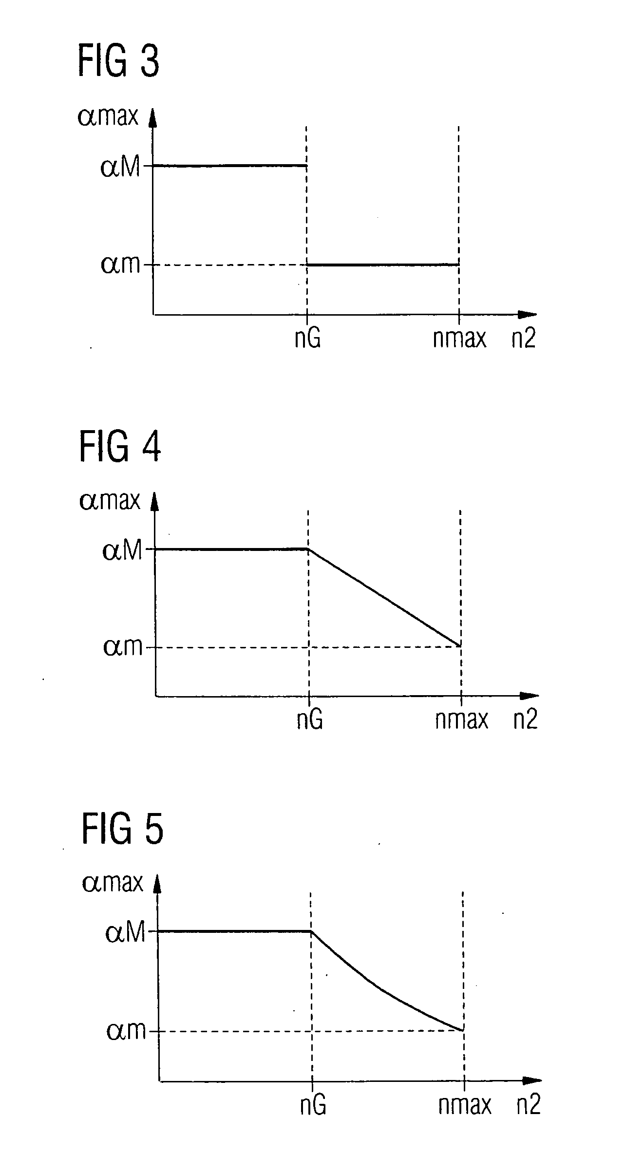
In principle, the controller can determine the acceleration curve numerically. However, advantageously, the controller can determine the acceleration curve analytically, which tends to be more accurate and also faster than a numerical computation.

Problems solved by technology

Although conventional rotation speed control methods operate satisfactorily, they are unable to completely eliminate residual contour errors, in particular, if the reference rotation speed is provided to the controller not only once, but continuously.

Method used


Image

  • Method for controlling a rotation speed of a slave drive, a corresponding controller and a corresponding machine
  • Method for controlling a rotation speed of a slave drive, a corresponding controller and a corresponding machine
  • Method for controlling a rotation speed of a slave drive, a corresponding controller and a corresponding machine

Examples


Embodiment Construction

Throughout all the Figures, same or corresponding elements are generally indicated by same reference numerals. These depicted embodiments are to be understood as illustrative of the invention and not as limiting in any way. It should also be understood that the drawings are not necessarily to scale and that the embodiments are sometimes illustrated by graphic symbols, phantom lines, diagrammatic representations and fragmentary views. In certain instances, details which are not necessary for an understanding of the present invention or which render other details difficult to perceive may have been omitted.

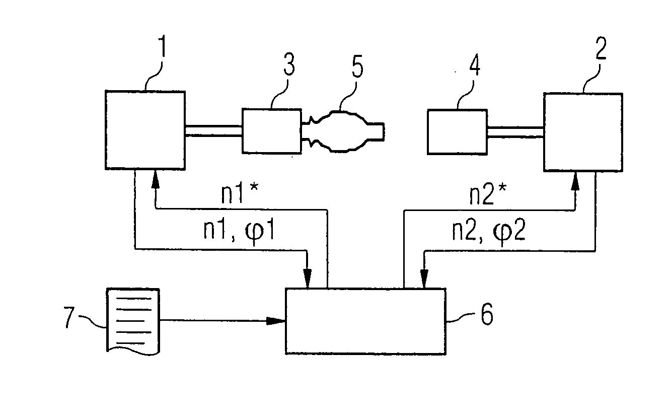
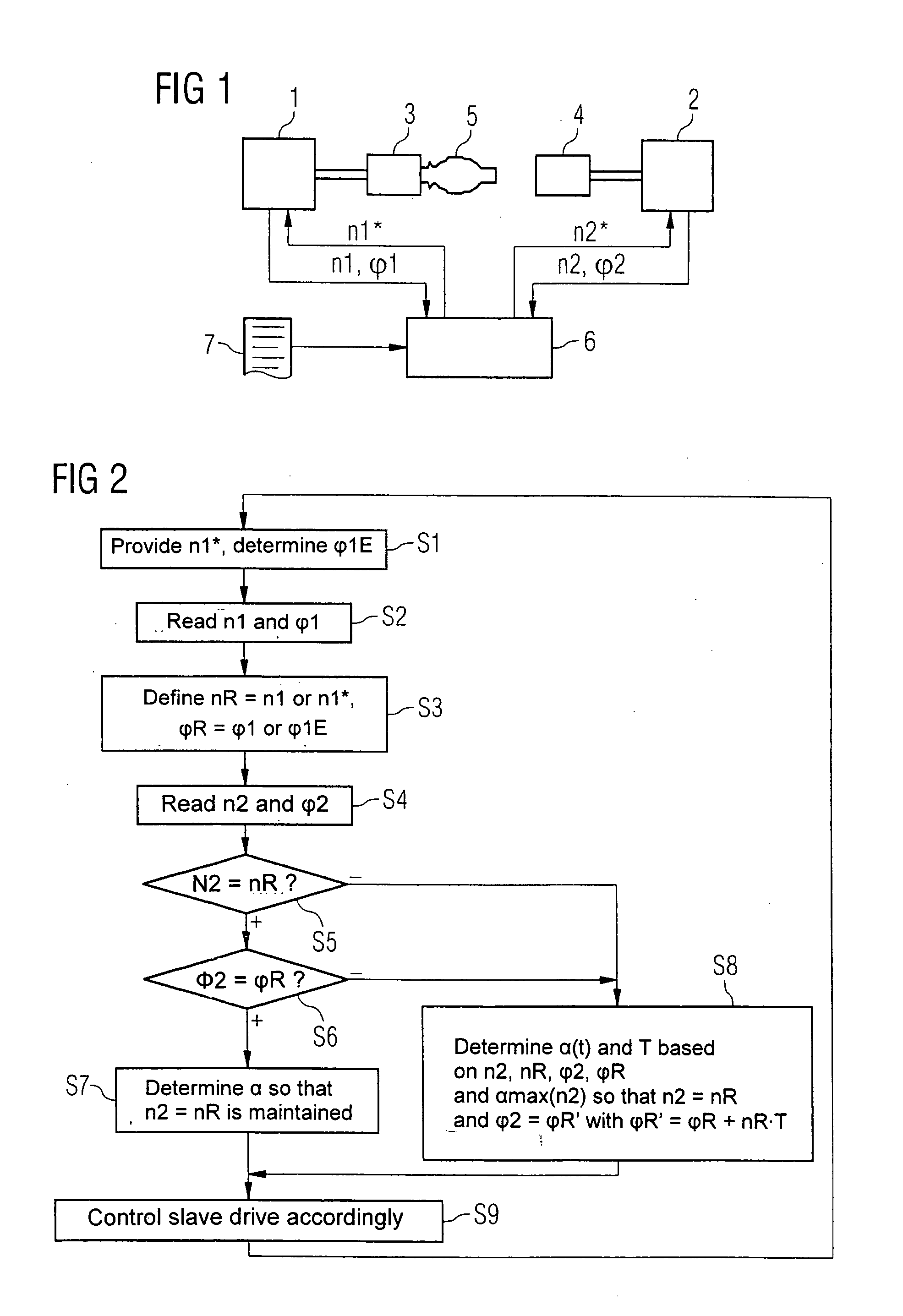
Turning now to the drawing, and in particular to FIG. 1, there is shown a machine, such as a turning machine or lathe as an example of a machine tool, with a master drive 1 and a slave drive 2. The master drive 1 drives a master element 3, for example a rotating tool holder 3. The slave drive 2 drives a slave element 4, which can be a rotating workpiece holder 4. The master eleme...


PUM


Abstract

A method for controlling the rotation speed of a slave drive is described, where a reference rotation speed and a reference position is provided to a controller. The controller determines an estimated acceleration curve for the slave drive based on an instantaneous rotation speed, an instantaneous position and a maximum rotation-speed-dependent acceleration of the slave drive. The estimated acceleration curve for the slave drive is hereby determined so that after a compensation time, the rotation speed of the slave drive is equal to the reference rotation speed and the position of the slave drive is also equal to an expected reference position, which is determined by the controller based on the reference position, the reference rotation speed and the compensation time.

Description

CROSS-REFERENCES TO RELATED APPLICATIONS This application claims the priorities of German Patent Applications, Serial Nos. 103 41 091.0, filed Sep. 5, 2003, and 10 2004 025 118.5, filed May 21, 2004, pursuant to 35 U.S.C. 119(a)-(d), the disclosure of which is incorporated herein by reference. BACKGROUND OF THE INVENTION The present invention relates to a method for controlling the rotation speed of a slave drive, and also to a controller for a slave drive carrying out the method and a machine with a slave drive controlled by such controller. Nothing in the following discussion of the state of the art is to be construed as an admission of prior art. A method for controlling the rotation speed is disclosed, for example, in European patent publication no. EP 0 704 781 A, which describes a drive for, for example, a machine tool, which is controlled so as to minimize contour errors by matching a feed rate to the reference rotation speed at a predetermined point in time. Although co...

Claims


Application Information

Patent Timeline
IPC IPC(8): G05B19/408G05B19/416H02P1/54
CPCG05B2219/43074G05B19/416
Inventor TOLKMITT, TOMLEVIE, HEINO DE
Owner SIEMENS AG
Learn More