This helps you quickly interpret patents by identifying the three key elements:
Problems solved by technology
Method used
Benefits of technology
Benefits of technology
[0012] According to the above-described projector apparatus, an image containing an alert may be displayed when the control unit determines that the relative distance exceeds the predetermined amount. With the above, it is possible to readily determine in advance the occurrence of significant distortion and / or blur.
[0013] According to the above-described projector apparatus, an image having a predetermined area thereof deleted may be displayed when the control unit determines that the relative distance exceeds the predetermined amount. With the above, it is possible to display an image with little distortion and / or blur.
[0014] According to the above-described projector apparatus, an image to be displayed having a predetermined area thereof expressed in black may be displayed when the control unit determines that the relative distance exceeds the predetermined amount. With the above, it is possible to display an image with little distortion and / or blur.
Problems solved by technology
Such large and heavy projector apparatus cannot usually be easily moved once installed.
Specifically, as shown in FIG. 12, the angle of view is distorted; the overall brightness is inconsistent; and blur expands due to the focus not being properly adjusted.
The larger the relative distance between the central line of the incident light and the optical axis of the lens unit becomes, in other words, the larger the distance between the point where the optical axis of the lens unit contacts with the wall on which the screen provided thereon and the image actually shown on the screen becomes, the more serious the above-described problem of distortion and / or blur becomes.
However, with the image sliding excessively, the viewer of the image may recognize obvious distortion and / or blur of the image, which could be a practical problem.
As described above, the above-described projector apparatus has a possibility that positional adjustment of an image on the screen may result in distortion and blur of the image, which are large enough to cause a practical problem.
Method used
Image
Click on the blue label to locate the original text in one second.
Reading with bidirectional positioning of images and text.
Examples
first embodiment
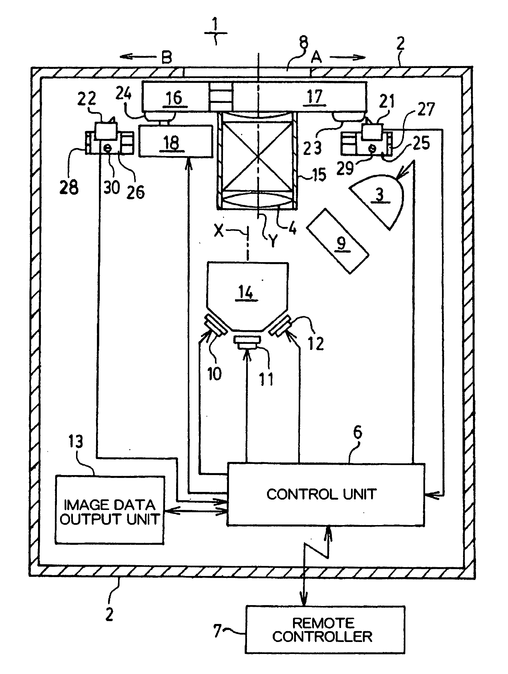
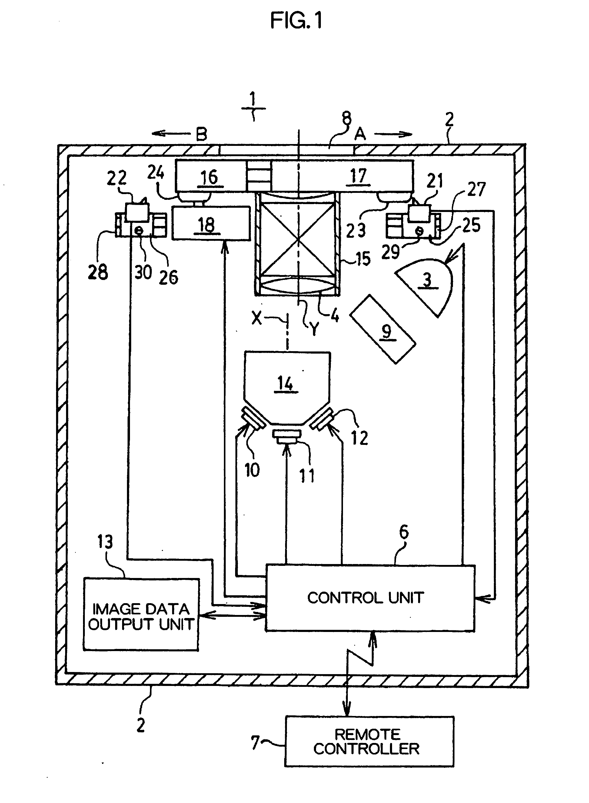
[0029]FIG. 1 shows a structure of a projector apparatus 1 according to a first embodiment. As shown in FIG. 1, the projector apparatus 1 comprises a control unit 6, a casing 2, a light source 3, and a lens unit 4.
[0030] The control unit 6 controls an overall operation of the projector apparatus 1, and can receive an instruction from the operator and operate accordingly. An instruction from the operator is input via the remote controller 7. The remote controller 7 can be removed from and attached to the casing 2 to be described later, and serves, when mounted to the casing 2, as an operating device of the main body of the projector apparatus 1, and when separated from the casing, as a remote controller. Obviously, a separate operating device may be mounted to the casing 2 to be described later. The remote controller 7 has a cursor button, or the like, and is used to input an instruction to slide the slider member 16, to be described later, for positional adjustment of the image on t...
second embodiment
[0074] In the following, a second embodiment of the present invention will be described while referring to the accompanying drawings. In the second embodiment, the distorted or blurred portion of the image, caused by sliding the image, is automatically deleted to some extent.
[0075]FIGS. 8 and 9 show a structure of a projector apparatus 1 according to the second embodiment of the present invention. In order to facilitate understanding, structural elements identical to those in FIG. 1 are given identical reference numerals, with detailed description not repeated here. The projector apparatus shown in FIG. 8 comprises a measurement unit 31 for measuring the slide amount of the slider member 16, instead of the elements, such as the limiters 21, 22, the pressing bodies 23, 24, and so forth, for detecting a predetermined slide amount of the slider members 16.
[0076] The measurement unit 31 comprises a scale body 32, a light emitting device 33, a light receiving element 34, and a holding ...
PUM
Abstract
A projector apparatus, comprising a light converging unit (14) for converging image light for formation of a predetermined image; a lens unit (4) for passing through the image light from the light converging unit (14) so that an image of a predetermined magnification is displayed on a screen; a moving unit (5) for changing a relative distance between the light converging unit (14) and the lens unit (4) to adjust a position of the image displayed on the screen by the lens unit (4); and a control unit (6) for determining whether or not the relative distance changed by the moving unit exceeds a predetermined amount.
Description
TECHNICAL FIELD [0001] The present invention relates to projector apparatuses, and in particular to a projector apparatus capable of changing a position on a screen to which an image is projected. BACKGROUND ART [0002] In recent years, commercial use projector apparatuses, in particular, become larger and heavier, following the trend of projecting larger images and enhancing the quality thereof. Such large and heavy projector apparatus cannot usually be easily moved once installed. [0003] With such background, Japanese Patent Laid-open Publication No. Hei 9-138377, for example, discloses a structure capable of changing a relative distance between the central line of the luminous flux of image light and the optical axis of the lens unit so that an image can be projected onto a desired position on the screen from the projector apparatus with a main body thereof fixedly installed. This structure can slide the position on the screen, onto which the image light is projected from the proj...
Claims
Application Information
Patent Timeline
Application Date:The date an application was filed.
Publication Date:The date a patent or application was officially published.
First Publication Date:The earliest publication date of a patent with the same application number.
Issue Date:Publication date of the patent grant document.
PCT Entry Date:The Entry date of PCT National Phase.
Estimated Expiry Date:The statutory expiry date of a patent right according to the Patent Law, and it is the longest term of protection that the patent right can achieve without the termination of the patent right due to other reasons(Term extension factor has been taken into account ).
Invalid Date:Actual expiry date is based on effective date or publication date of legal transaction data of invalid patent.

