
Method and de-interlacing apparatus that employs recursively generated motion history maps

a motion history map and video technology, applied in the field of methods and apparatus for deinterlacing interlaced video, can solve problems such as improper motion detection, picture quality problems, and multi-media capabilities of personal computers or other devices

Inactive Publication Date: 2005-04-14
ATI TECH INC
View PDF9 Cites 36 Cited by
  • Summary
  • Abstract
  • Description
  • Claims
  • Application Information

AI Technical Summary

Problems solved by technology

When such interlaced signals are received for display in a progressive display, such as a computer display or other suitable display, picture quality problems can arise especially when motion is occurring in the picture where inferior methods of de-interlacing are used.
A problem may exists for personal computers or other devices having multi media capabilities since interlaced video information received from conventional video tapes, cable television broadcasters, digital video discs and digital broadcast satellite systems must typically be de-interlaced for suitable display in a progressive display device.
However this limited amount of information can result in improper motion detection.
Using twice the memory to get eight fields of information would be too costly.
One problem with this described methodology is that the motion maps do not take into account pixel values for more than two consecutive same polarity fields.
This system also appears to require a large amount of memory to store a plurality of motion maps for each group of two same polarity fields.
Temporal interpolation (e.g. weave) is typically best suited if the video sequence consist of static images but does not work well with moving video.
Typical hardware solutions can limit the number of fields available to save on memory costs but may use complex logic to detect motion and de-interlace fields.

Method used


Image

  • Method and de-interlacing apparatus that employs recursively generated motion history maps
  • Method and de-interlacing apparatus that employs recursively generated motion history maps
  • Method and de-interlacing apparatus that employs recursively generated motion history maps

Examples


Embodiment Construction

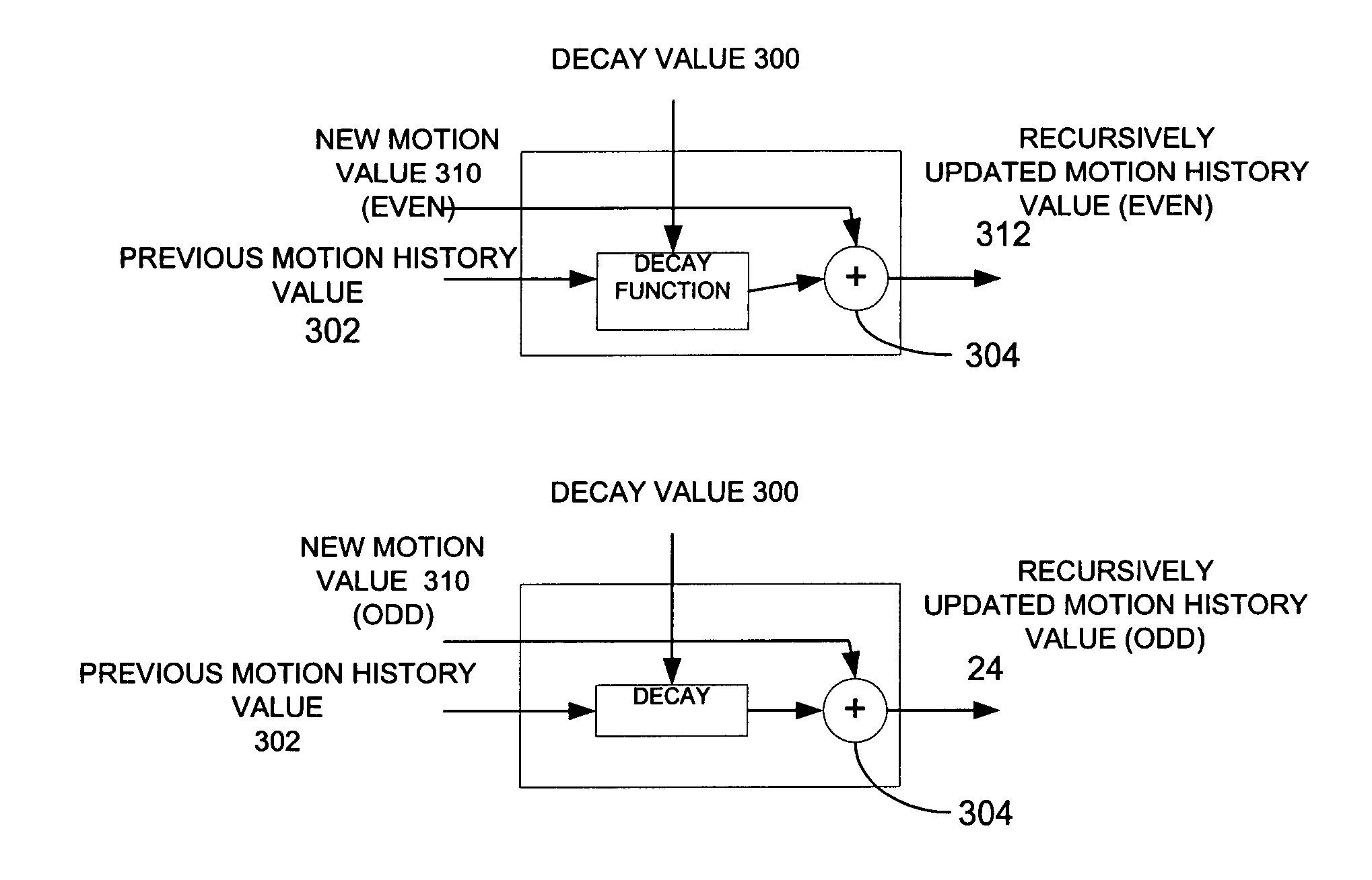
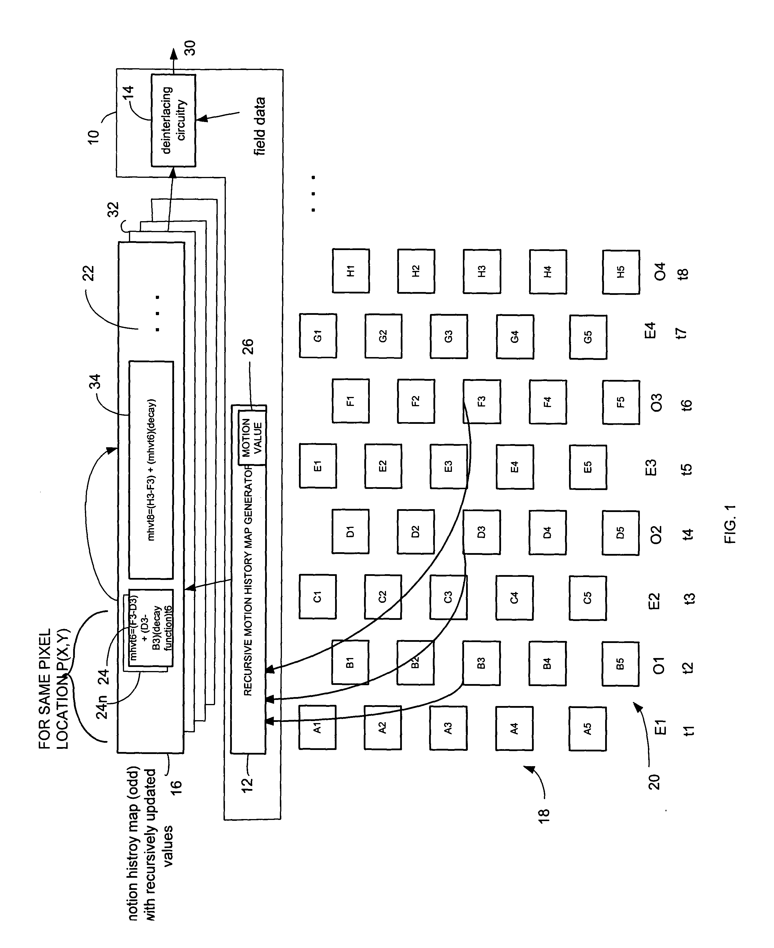
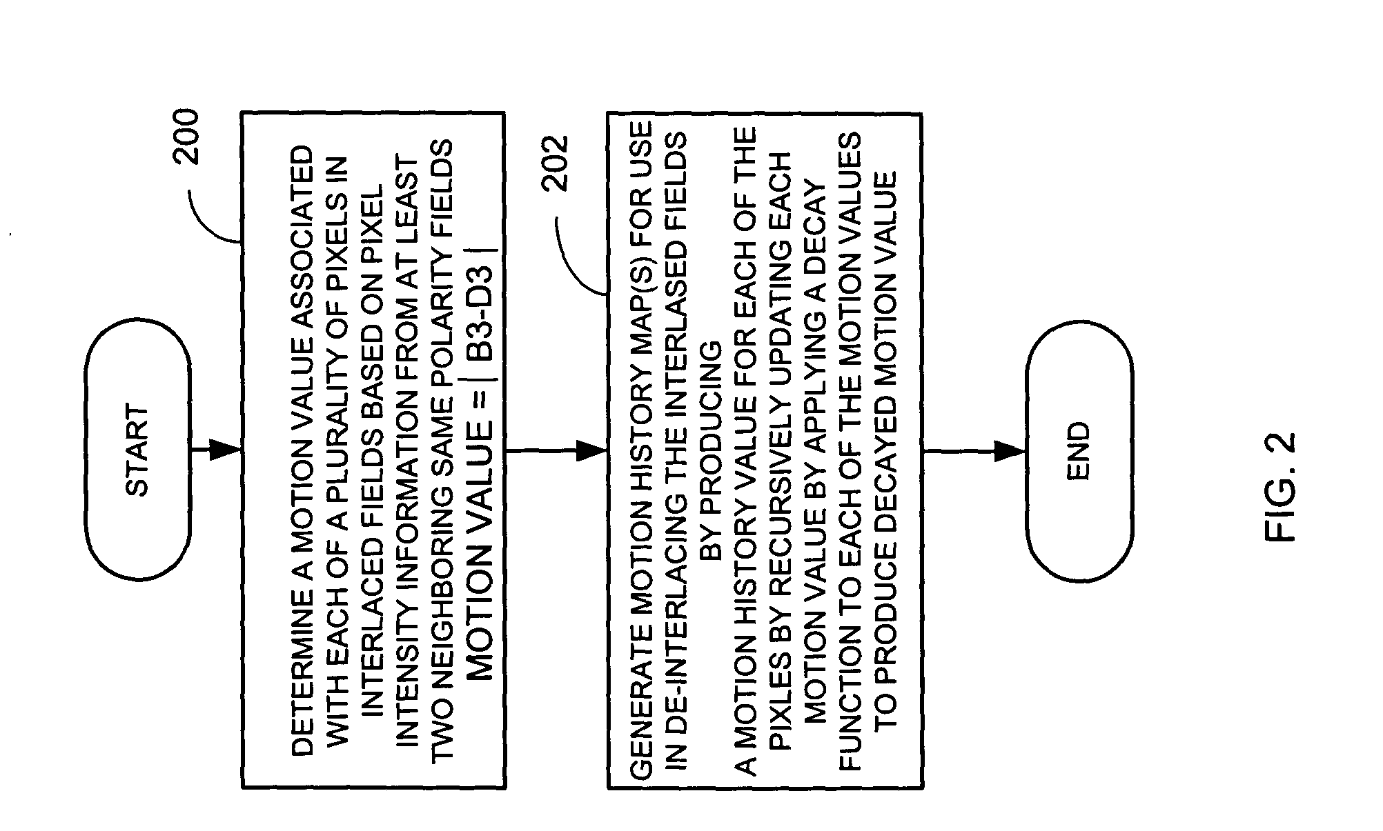
A de-interlacer includes recursive motion history map generating circuitry operative to determine a motion value associated with one or more pixels in interlaced fields based on pixel intensity information from at least two neighboring same polarity fields. The recursive motion history map generating circuitry generates a motion history map containing recursively generated motion history values for use in de-interlacing interlaced fields wherein the recursively generated motion history values are based, at least in part, on a decay function.

The de-interlacer also includes de-interlacing circuitry that utilizes the recursively generated motion history values stored in the motion history map to provide de-interlaced output pixel information. In one embodiment, the recursively generation motion history values are used to detect motion and to select whether weaved pixel should be used as the de-interlace technique. The application of the decay function allows for the continued recursiv...


PUM


Abstract

A de-interlacer includes recursive motion history map generating circuitry operative to determine a motion value associated with one or more pixels in interlaced fields based on pixel intensity information from at least two neighboring same polarity fields. The recursive motion history map generating circuitry generates a motion history map containing recursively generated motion history values for use in de-interlacing interlaced fields wherein the recursively generated motion history values are based, at least in part, on a decay function.

Description

FIELD OF THE INVENTION The invention relates generally to methods and apparatus for de-interlacing interlaced video, and more particularly, to methods and apparatus that de-interlace interlaced video using motion detection and / or motion estimation techniques. BACKGROUND OF THE INVENTION For computer monitors that are mostly non-interlaced or progressive type display devices, video images or graphic images must be displayed by sequentially displaying each successive line of pixel data sequentially for a frame of an image. In contrast, inter-laced display devices, such as conventional television displays, typically display images using even and odd line interlacing. The process of producing one progressive frame on every incoming interlaced field is called de-interlacing. When such interlaced signals are received for display in a progressive display, such as a computer display or other suitable display, picture quality problems can arise especially when motion is occurring in the p...

Claims


Application Information

Patent Timeline
IPC IPC(8): H04N5/14H04N5/44H04N7/01
CPCH04N5/144H04N7/014H04N7/0137H04N7/012
Inventor WONG, DANIEL W.SWAN, PHILIP L.DOSWALD, DANIEL
Owner ATI TECH INC
Learn More