Method for monitoring performance degradation state of stay cable anchor head based on fiber distributed measurement

A fiber optic distributed, cable-stayed anchor technology, applied in the direction of measuring force, measuring device, measuring the change force of the optical properties of the material when it is stressed, can solve the problems of real-time monitoring, damage, debonding, Defects and cracks, etc., to achieve the effect of continuous monitoring

Active Publication Date: 2016-09-07
宁波正信检测科技有限公司
View PDF4 Cites 8 Cited by
  • Summary
  • Abstract
  • Description
  • Claims
  • Application Information

AI Technical Summary

Problems solved by technology

[0004] In the prior art, the commonly used nondestructive monitoring methods mainly include: conventional ultrasonic testing method, ultrasonic imaging testing method, and infrared thermal wave testing method; these three nondestructive testing methods can detect internal defects of structures and bonding quality, but if the aforementioned The three methods are used for anchor head disease monitoring, and there are the following problems: First, the optimal application object of the above three methods is a regular and simple structure, and the anchor head belongs to a complex composite structure. There are still some problems in the detection; secondly, the non-destructive testing method can only be used for regular safety inspections, and cannot realize online real-time monitoring; in addition, the anchor head is a key component of the bearing, and its performance degradation is a gradual process, that is, From strong grip between steel wire and anchoring material, to weak grip, to debonding, defects and cracks, and finally failure, therefore, the most valuable non-destructive testing method is one that can detect performance degradation at an early stage Anchor head, so as to determine which stage of anchor head is currently in performance decline, and the above three methods do not have this ability

Method used


Image

  • Method for monitoring performance degradation state of stay cable anchor head based on fiber distributed measurement
  • Method for monitoring performance degradation state of stay cable anchor head based on fiber distributed measurement
  • Method for monitoring performance degradation state of stay cable anchor head based on fiber distributed measurement

Examples


Embodiment Construction

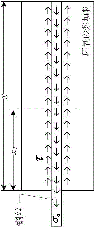
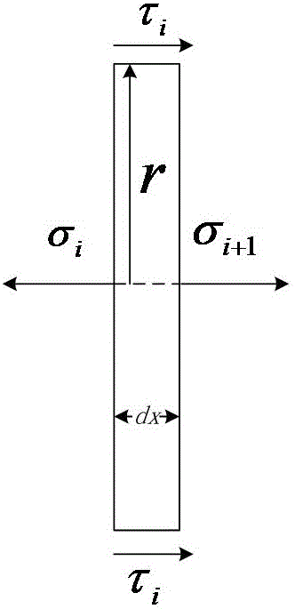
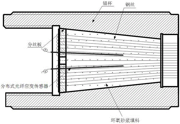
[0032] A cable-stayed cable anchor head performance degradation state monitoring method based on optical fiber distributed measurement. At the bottom of the cup, there are multiple reserved holes on the wire splitter plate. The inner end of the steel wire passes through the reserved holes on the wire splitter board and then the pier head is fixed. The multiple steel wires correspond to the reserved holes one by one. The area around the steel wire is filled with epoxy mortar filler; the innovation is that the method for monitoring the state of performance degradation of the stay cable anchor head includes:

[0033] 1) Multiple implantation holes are prefabricated on the solid part of the splitter board; during the anchor head production process, before pouring epoxy mortar filler, a thin strip of distributed optical fiber strain is implanted in each implantation hole Sensor, the axis of the distributed optical fiber strain sensor is parallel to the steel wire axis, the end of t...


PUM


Abstract

A method for monitoring performance degradation state of a stay cable anchor head based on fiber distributed measurement is characterized in that a distributed fiber strain sensor is imbedded in an anchor cup to acquire strain data, an initial stress decay function is obtained through the strain data, a current strain decay function is obtained in real time through the strain data during a subsequent process, a quantitative index for health level of the anchor head is computed according to the initial stress decay function and the current stress decay function, and thus real-time monitoring is achieved for anchor head performance; the invention has the advantages that the method monitoring performance degradation state of stay cable anchor head based on fiber distributed measurement is provided and the method allows timely discovery and continuous monitoring for anchor head disease damage.

Description

technical field [0001] The invention relates to an anchor head performance monitoring technology, in particular to a cable-stayed cable anchor head performance degradation state monitoring method based on optical fiber distributed measurement. Background technique [0002] As the main load-bearing structure of the cable-stayed bridge, the cable-stayed cable has the advantages of large load-bearing capacity, light weight, compact size, good flexibility, and convenient use; the anchor head is the stress connection point between the cable and the long-span structure, and is the It is the most complex load-bearing structure in the world; although the structure of the cable-stayed anchor head and its manufacturing process have considered the durability requirements, it still inevitably suffers from performance degradation. According to research and analysis, the performance degradation of the anchor head is mainly as follows: Two situations: ① In the anchor head structure, the sh...

Claims


Application Information

Patent Timeline
Patent Type & Authority Applications(China)
IPC IPC(8): G01L1/24
CPCG01L1/247
Inventor 吴俊舒岳阶余葵马希钦周远航
Owner 宁波正信检测科技有限公司
Why Eureka
Try Eureka