Sensing system of fiber strain

A technology of sensing system and optical fiber strain, which is applied in the direction of using optical devices to transmit sensing components, using optical devices, measuring devices, etc., can solve problems such as failure to work normally, excessive signal attenuation, and being affected by temperature, and achieve anti-electromagnetic Strong interference ability, small influence of humidity changes, stable and reliable data

Inactive Publication Date: 2006-04-19
上海安文桥梁检测技术有限公司
View PDF0 Cites 6 Cited by
  • Summary
  • Abstract
  • Description
  • Claims
  • Application Information

AI Technical Summary

Problems solved by technology

However, in practical applications, there are still some serious problems, such as being susceptible to moisture and temperature; susceptible to interference from surrounding electromagnetic fields, unable to work normally in strong electromagnetic fields or electrical noise environments; long-distance transmission, excessive signal attenuation, etc. Wait

Method used


Image

  • Sensing system of fiber strain
  • Sensing system of fiber strain
  • Sensing system of fiber strain

Examples


specific Embodiment 1

[0022] In order to simulate the stressed state of the bridge to test the effectiveness of the optical fiber strain sensing system of the present invention, we made a set of test experimental device-equal strength cantilever beam. The material is 65Mn steel, and its elastic modulus E is measured to be 200.5Gpa.

[0023] The width b of the consolidated end of the equal-strength cantilever beam is 72mm, the thickness h is 6mm, and the length l is 350mm. Let the hanging weight P be W = b h 2 6 = 36 × 6 2 6 = 432 m m 3 1kg, then:

[0024] Section modulus:

[0025] Bending distance: M=Pl=9.8×1×350=3430N-mm

[0026] Theoretical stress: σ = ...

specific Embodiment 2

[0035] Temperature condition experiment: place the small cantilever beam pasted with the optical fiber strain sensor of the present invention in the experiment box, after the temperature of the experiment box reaches the calibrated temperature and stabilizes, take it out and immediately carry out the loading experiment and record the data.

[0036] Humidity condition experiment: place the optical fiber strain sensor of the present invention in the concrete curing room and set the temperature and humidity to make it stable, and record data at the same time.

[0037] The measured data of high-temperature and low-temperature cantilever beam loading experiments are as follows:

[0038] temperature(℃)

[0039] Optical fiber strain sensor humidity measured data table of the present invention

[0040] time (minutes)

[0041] Experiments show that the optical fiber strain sensor of the invention can adapt to the temperature environment of -50°C to 90°C and the applic...


PUM


Abstract

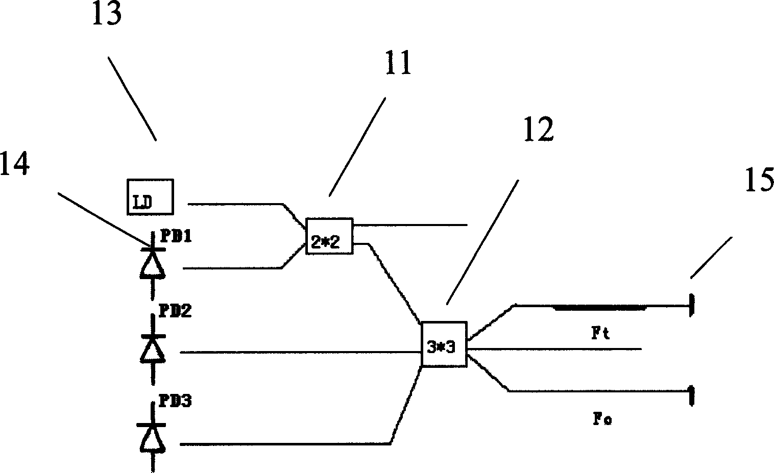
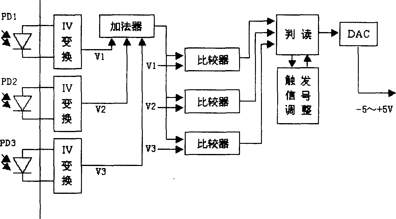
The sensing system of fiber strain is composed of optical fiber sensor, photovoltaic conversion circuit, and data processor. Characters are that through optical fiber, optical fiber sensor is connected to the photovoltaic conversion part partially; through data line, the photovoltaic conversion circuit is connected to the data processing circuit; Michelson type sensor is adopted in the optical fiber sensor. Advantages are: high anti electromagnetic interference, sensitivity, small influence from temperature and humidity, transmissibility of remote distance, etc. The system is suitable for real-time safe and fine monitoring and alarming large-scale structure in medium or long term.

Description

technical field [0001] The invention relates to the field of optoelectronics, in particular to the field of optical sensors, in particular to an application system of an optical fiber sensor, in particular to an optical fiber strain sensing system used for strain measurement at key parts of bridges. Background technique [0002] In the prior art, various resistance strain sensors are most commonly used in strain measurement at key parts of bridges. Although this type of sensor has a long history of application, it has accumulated rich experience. However, in practical applications, there are still some serious problems, such as being susceptible to moisture and temperature; susceptible to interference from surrounding electromagnetic fields, unable to work normally in strong electromagnetic fields or electrical noise environments; long-distance transmission, excessive signal attenuation, etc. Wait. Contents of the invention [0003] The technical problem to be solved by ...

Claims


Application Information

Patent Timeline
Patent Type & Authority Applications(China)
IPC IPC(8): G01B11/16G01D5/26
Inventor 陈前媚雷春奇潘晔峰
Owner 上海安文桥梁检测技术有限公司
Why Eureka
Try Eureka