
Apparatus and method for detecting opaque logos within digital video signals

a technology of opaque logos and digital video signals, applied in the field of digital video display, can solve problems such as unreliability of detection of logos/non-logo pixels

Inactive Publication Date: 2005-04-14
SAMSUNG ELECTRONICS CO LTD
View PDF6 Cites 36 Cited by
  • Summary
  • Abstract
  • Description
  • Claims
  • Application Information

AI Technical Summary

Benefits of technology

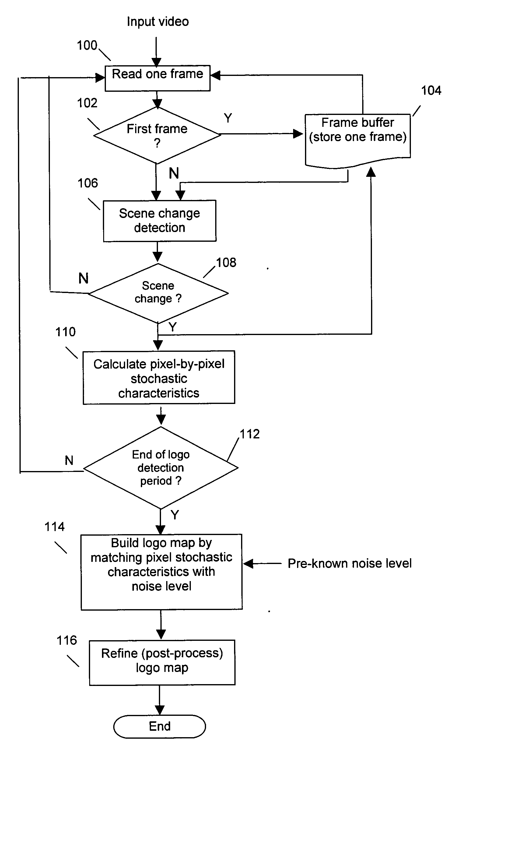
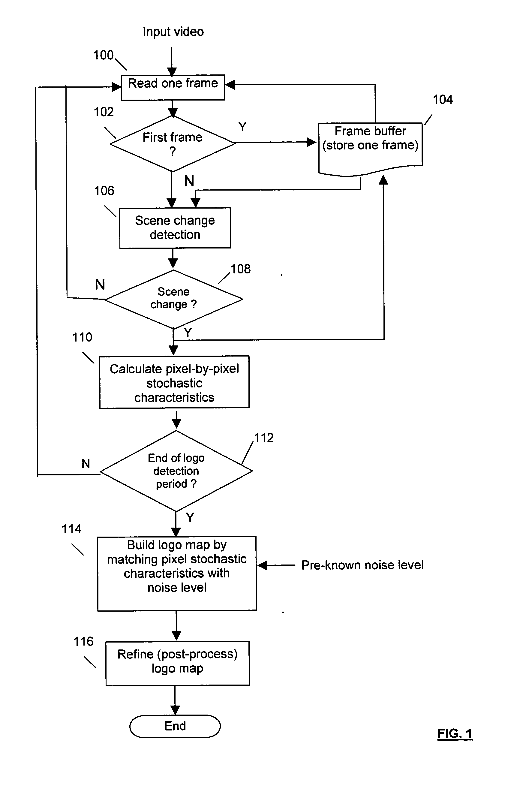
The present invention addresses the above needs. In one embodiment, the present invention provides a detection method that allows detecting an opaque logo after it has appeared in the digital video program for a short period of time, by deriving and analyzing the stochastic characteristics of the video signal along the temporal axis. The first incoming video image frame is stored in a buffer. Thereafter, incoming frames are passed to a scene change detection module. To determine if there is a scene change in the incoming (current) frame relative to a previous (reference) frame, the difference between the incoming frame and the previous frame stored in the buffer is measured based on pixel intensities. If the difference is high (i.e., a scene change occurred), then the current frame is used for the next step analysis. Otherwise, the current frame is discarded and the next incoming frame is read in and examined by determining the difference between this incoming frame and the buffered reference frame.
According to the present invention, temporal stochastic characteristics are used to determine if a pixel belongs to the logo or background video content. The standard deviation of the noise is utilized to help logo / non-logo decision when the digital video signal is noisy. A post-processing scheme is applied to refine the logo map, such that the final logo map is more resistant to noise and is smoother. Therefore, a detection method according to the present invention is very reliable, which can detect logos in very noisy videos.

Problems solved by technology

However, there may be some unreliably detected logo / non-logo pixels, requiring application of a prost-processing scheme to refine the logo map such that it is more resistant to noise.

Method used


Image

  • Apparatus and method for detecting opaque logos within digital video signals
  • Apparatus and method for detecting opaque logos within digital video signals
  • Apparatus and method for detecting opaque logos within digital video signals

Examples


example observations

From example observations, the number of logo pixels in a frame is mostly less than e.g. 20% of the total number of pixels in the frame. Because pixel intensity value changes in the logo area should not contribute to the scene change, in one example the threshold t2 can be set to about 80% in the real-world applications. Further, the larger the threshold t2, the fewer scene changes will be detected.

FIG. 4 shows a flow chart of the steps of an example process for calculating the stochastic characteristic of each pixel in the video frame in the temporal domain, according to the present invention. Starting from the first in the current frame, the difference d(t) in pixel intensity between the pixel in the current frame and a corresponding one in the reference frame is calculated as

d(t)=p(t)−p(t−τ)

in step 400, wherein p(t) denotes the pixel intensity value in the current frame t, p(t−τ) denotes the corresponding pixel intensity value in the reference frame t−τ. If the pixel with inte...


PUM


Abstract

A detection method and system that allows detecting an opaque logo after it has appeared in the digital video program for a short period of time, by deriving and analyzing the stochastic characteristics of the video signal along the temporal axis.

Description

FIELD OF THE INVENTION The present invention relates to the field of digital video display, and more particularly, to a method for tracking the display and disappearance of detected logos. BACKGROUND OF THE INVENTION Increasingly, television broadcast signals include logos that are displayed on television screens over the broadcast programs as station identification. If logos stay on the screen for considerably long periods of time without change in their intensities, colors, patterns and locations, they may be annoying, and can cause problems such as the well-known screen burn on High Definition TV (HDTV) sets. In general, logos are classified into three types: opaque logos, transparent logos and animated logos. Because transparent and animated logos change their brightness and colors along with the background video content, or move around from time to time, they are unlikely to cause screen burn on HDTV sets. By contrast, opaque logos are more problematic, because they usually s...

Claims


Application Information

Patent Timeline
IPC IPC(8): G06K9/32H04N5/44H04N5/14
CPCH04N5/147G06K9/3266G06V20/635H04N5/44
Inventor LIU, SHANKIM, YEONG-TAEG
Owner SAMSUNG ELECTRONICS CO LTD
Learn More