Studfinder and laser line layout tool

a laser line layout and studfinder technology, applied in the field of construction tools, can solve the problems of requiring the participation of more than one worker and frequent time-consuming operations

Active Publication Date: 2005-04-14
STANLEY WORKS THE
View PDF22 Cites 61 Cited by
  • Summary
  • Abstract
  • Description
  • Claims
  • Application Information

AI Technical Summary

Benefits of technology

[0007] One aspect of the invention is simply directed to the combination of a stud finder and a laser level device integrated into one tool.

Problems solved by technology

Layout operations often involve surfaces and structures that are difficult to access (e.g., high ceilings and ceiling joists).
These operations are therefore frequently time consuming and require the participation of more than one worker.

Method used


Image

  • Studfinder and laser line layout tool
  • Studfinder and laser line layout tool
  • Studfinder and laser line layout tool

Examples


Embodiment Construction

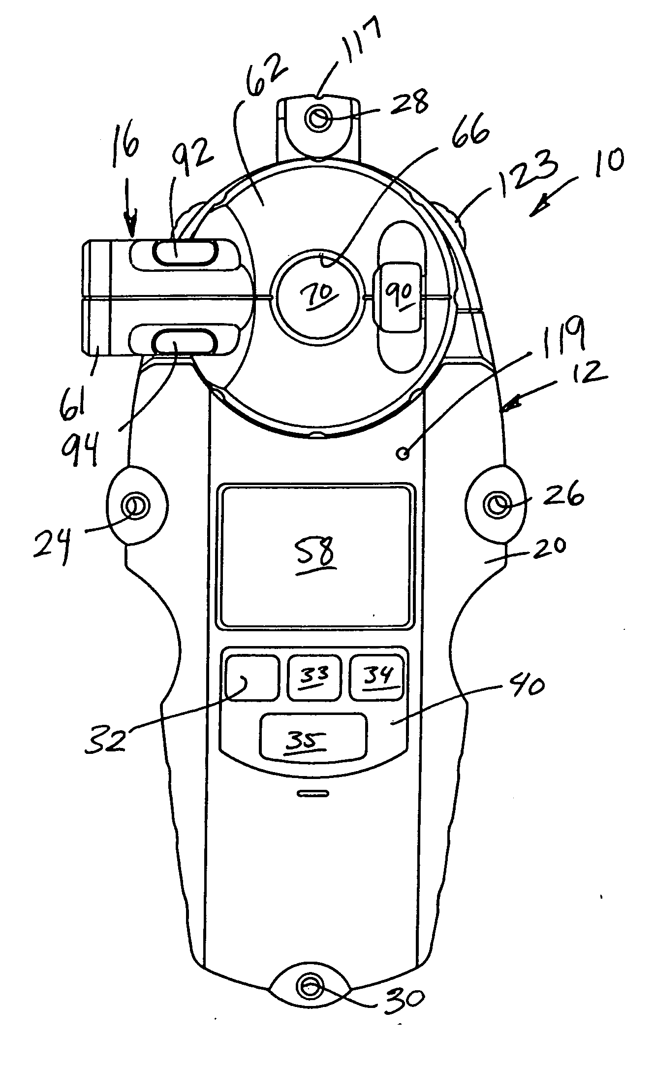
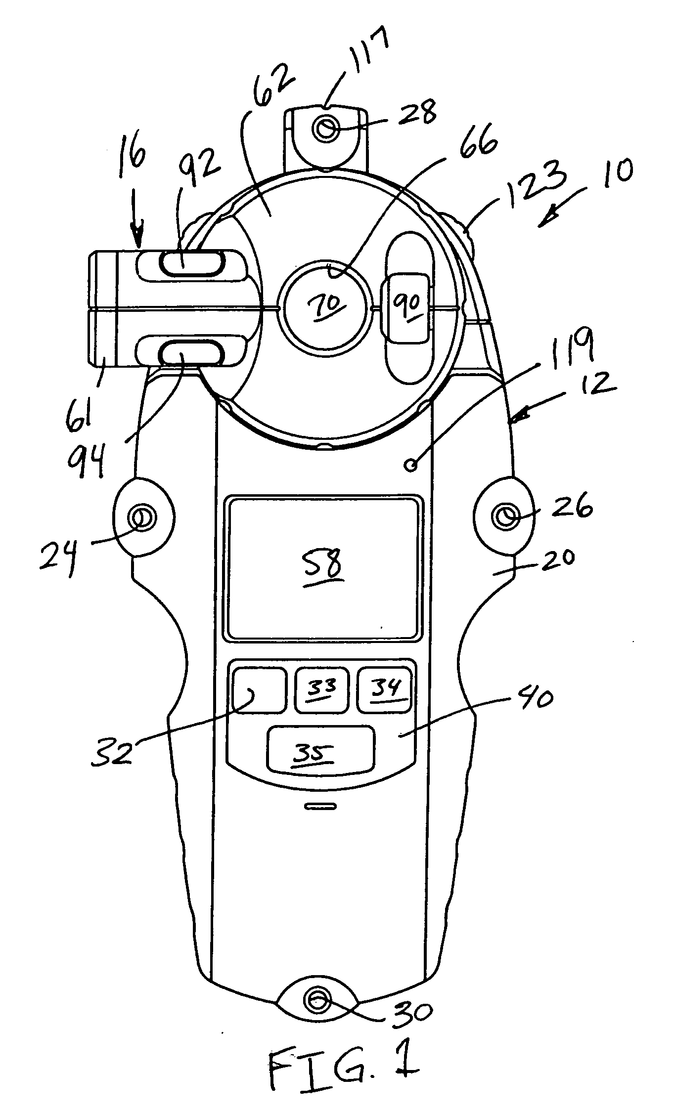
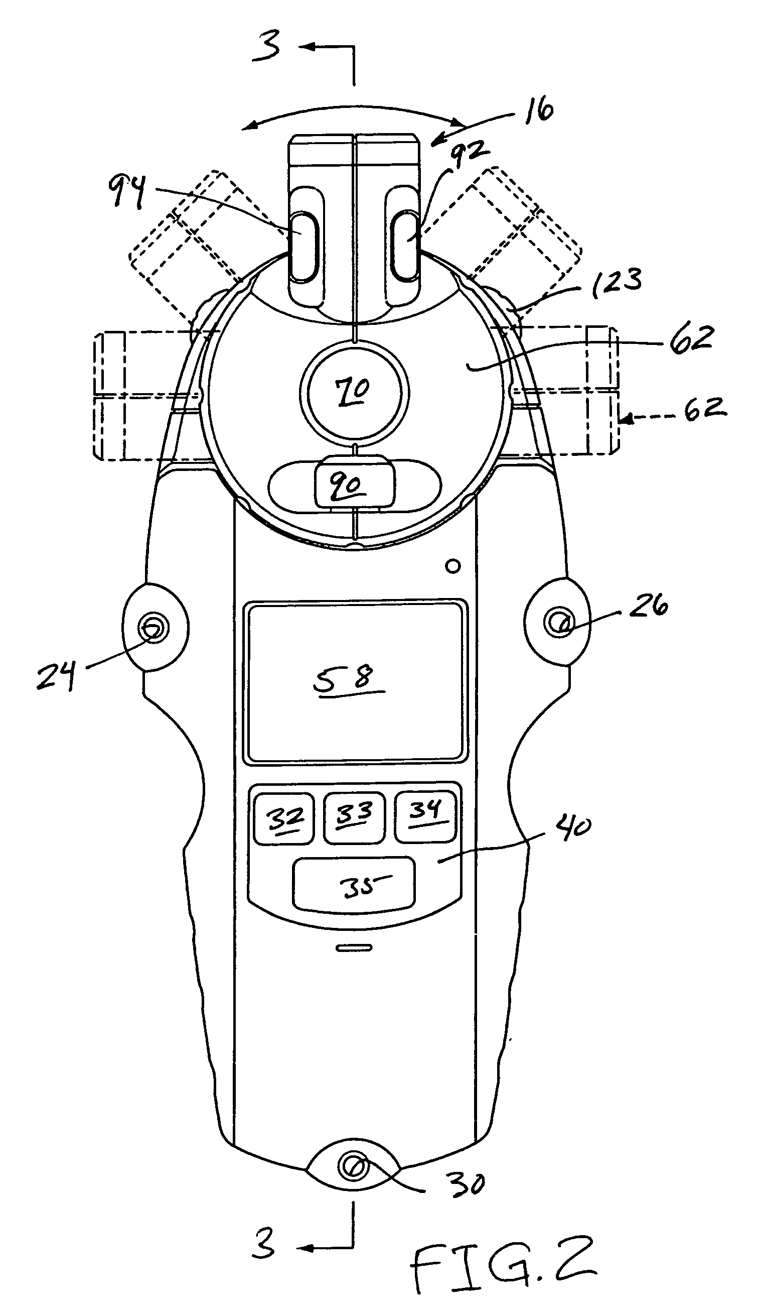
[0022]FIG. 1 is a front plan view illustrating an example of a portable, handheld tool 10 which embodies some of the principles of the present invention. The layout tool 10 includes a main body 12, an electronic object detector 14 (see FIG. 6) carried by and housed within the main body 12 and a light source 16 carried by the main body 12. The tool 10 includes an angular orientation mechanism (e.g., level vials 90, 92 and / or 94) operable to enable a worker to orient a line of light emitted by the light source 16 and / or to orient the main body 12.

[0023] The object detector 14 may be operated to detect the location of an object or of an edge of an object (e.g., a stud, joist, beam, pipe, wire) hidden from view behind a surface such as a wall, ceiling or floor surface. The light source 16 projects a line of light on the surface and may be used to assist a worker during a layout or stud finding operation. More specifically, the light source 16 may be operable to project a plane of light...


PUM


Abstract

A layout tool includes an object detector constructed and arranged to detect the location of a vertically extending edge portion of an object hidden from view behind a generally vertically extending wall surface, a light source that is capable of projecting a line of light along the wall surface, and an angular orientation mechanism operably coupled to the light projection mechanism. The angular orientation mechanism is operable to establish that the line of light is vertical. The light source and the object detector are operatively interengaged such that when a vertically extending edge is detected by the object detector, a vertically extending line of light projected on the surface by the light source indicates the location of a vertically extending edge portion of the hidden object.

Description

FIELD OF THE INVENTION [0001] The present invention is generally related to construction tools and to methods for using the same. BACKGROUND OF THE INVENTION [0002] Construction and home improvement projects often require the ability to determine the location of structures hidden from view (e.g., studs, joists, beams, or wires hidden behind a wall board) and / or to survey and mark an area or a surface to guide the construction process. Prior to mounting shelves on a wall, for example, a worker may wish to determine the location of hidden structural members (e.g., studs) behind the wall surface (e.g., sheetrock) which can provide structural support for the shelves and may wish to establish markings on the wall which indicate where the shelves should be anchored and positioned on the wall during installation. Floors and ceilings may be marked to indicate the locations of joists and / or may be marked with guidelines before a covering (e.g., floor or ceiling tile) is installed. [0003] Lay...

Claims


Application Information

Patent Timeline
Patent Type & Authority Applications(United States)
IPC IPC(8): G01B7/00G01B11/00G01B11/26G01C1/00G01C9/06G01C15/00G01V3/08G01V3/15
CPCG01C15/00G01C9/06G01V3/15
Inventor MURRAY, JOHN C.
Owner STANLEY WORKS THE
Why Eureka
Try Eureka