Laser trim and compensation methodology for passively aligning optical transmitter

a passive alignment and optical transmitter technology, applied in electromagnetic transmission, semiconductor lasers, electromagnetic transmission, etc., can solve the problems of invalidating calibration and operating points set at one temperature at other temperatures, and fluctuating temperatures. significant,

Active Publication Date: 2005-04-14
NAT SEMICON CORP
View PDF31 Cites 24 Cited by
  • Summary
  • Abstract
  • Description
  • Claims
  • Application Information

AI Technical Summary

Benefits of technology

[0007] In one method embodiment, a scheme for trimming and compensation of a laser emitter in a fiber optic link is disclosed. The method involves determining a base power level for a population of lasers using data models that characterize laser performance for the population of lasers and determining a relationship between modulation current (Imod) and temperature using the data models of laser performance. The method involves providing a selected laser device that is incorporated in a fiber optic link. A relationship between target average power and temperature for a specific laser device over a range of temperatures using the base power level is determined. Laser performance is adjusted based on the temperature, target average power, and modulation current (Imod).
[0008] Another method embodiment involves providing data models that characterize laser performance for a population of lasers. The models are generated using laser performance data obtained from measurements of laser properties taken from a sample population of lasers. A base power level is determined using information from the data models and from a p

Problems solved by technology

However, in ordinary course of operation diode temperatures can fluctuate significantly.
This

Method used


Image

  • Laser trim and compensation methodology for passively aligning optical transmitter
  • Laser trim and compensation methodology for passively aligning optical transmitter
  • Laser trim and compensation methodology for passively aligning optical transmitter

Examples


Embodiment Construction

[0031] The present invention has been particularly shown and described with respect to certain embodiments and specific features thereof. The embodiments set forth hereinbelow are to be taken as illustrative rather than limiting. It should be readily apparent to those of ordinary skill in the art that various changes and modifications in form and detail may be made without departing from the spirit and scope of the invention.

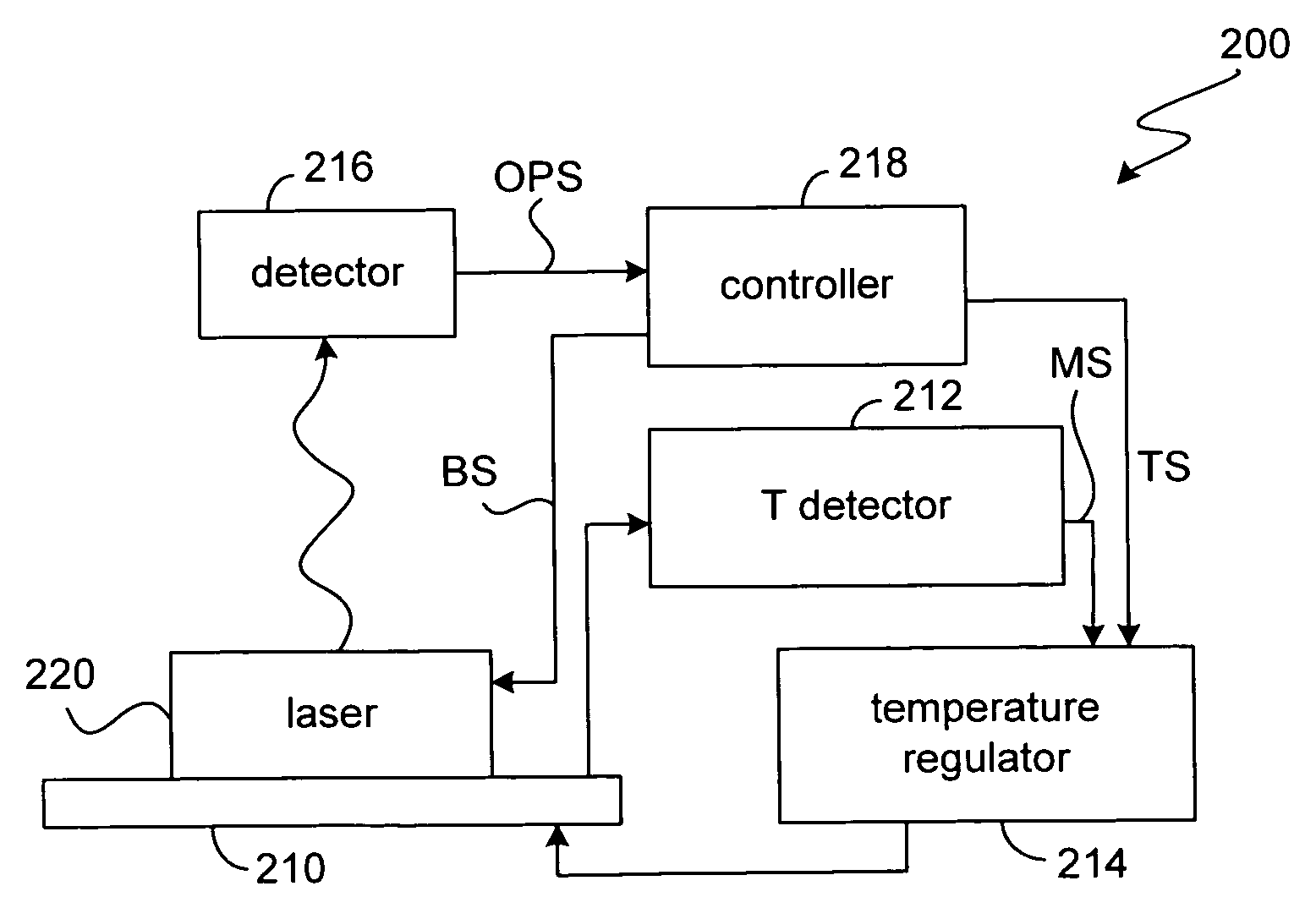
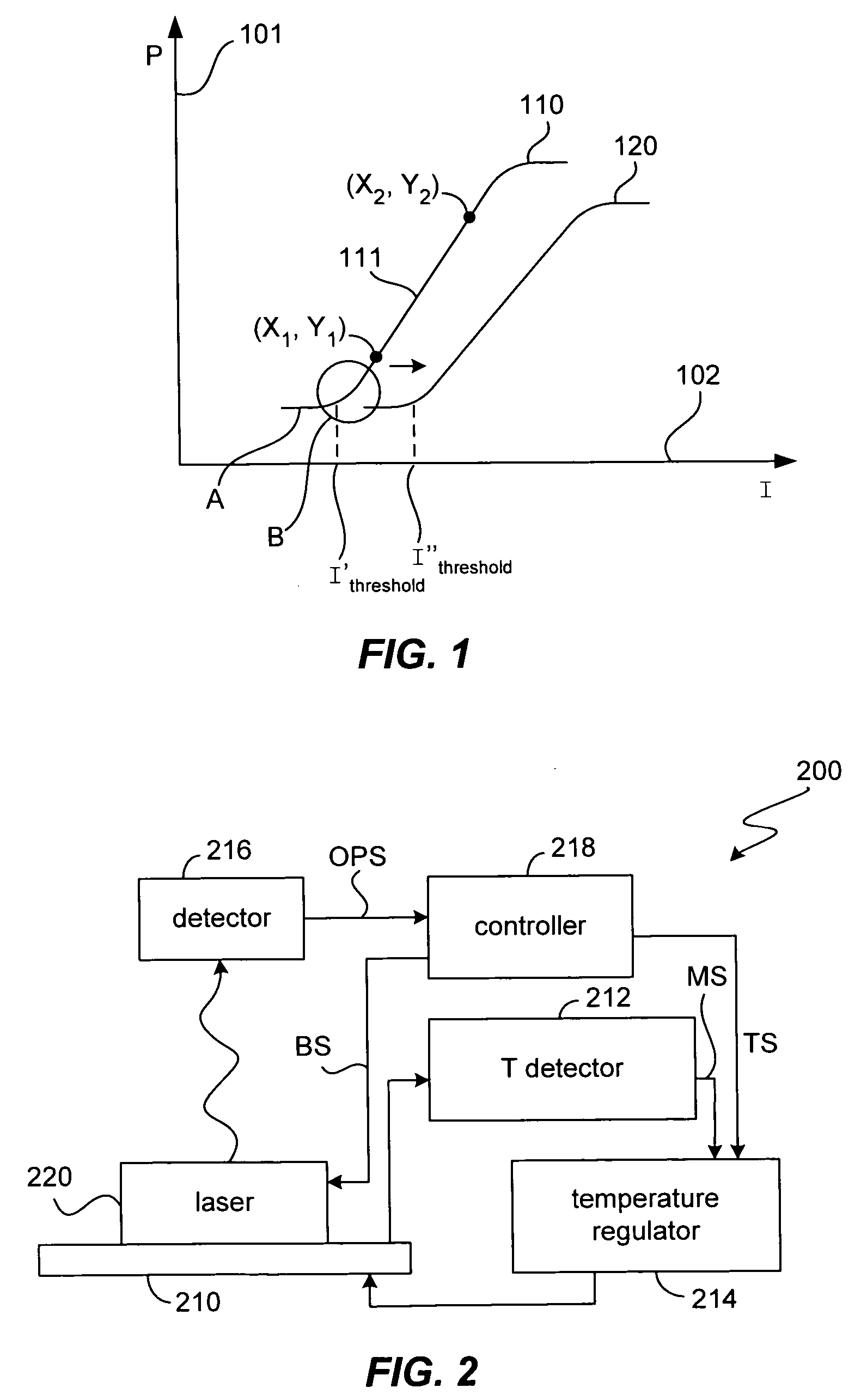
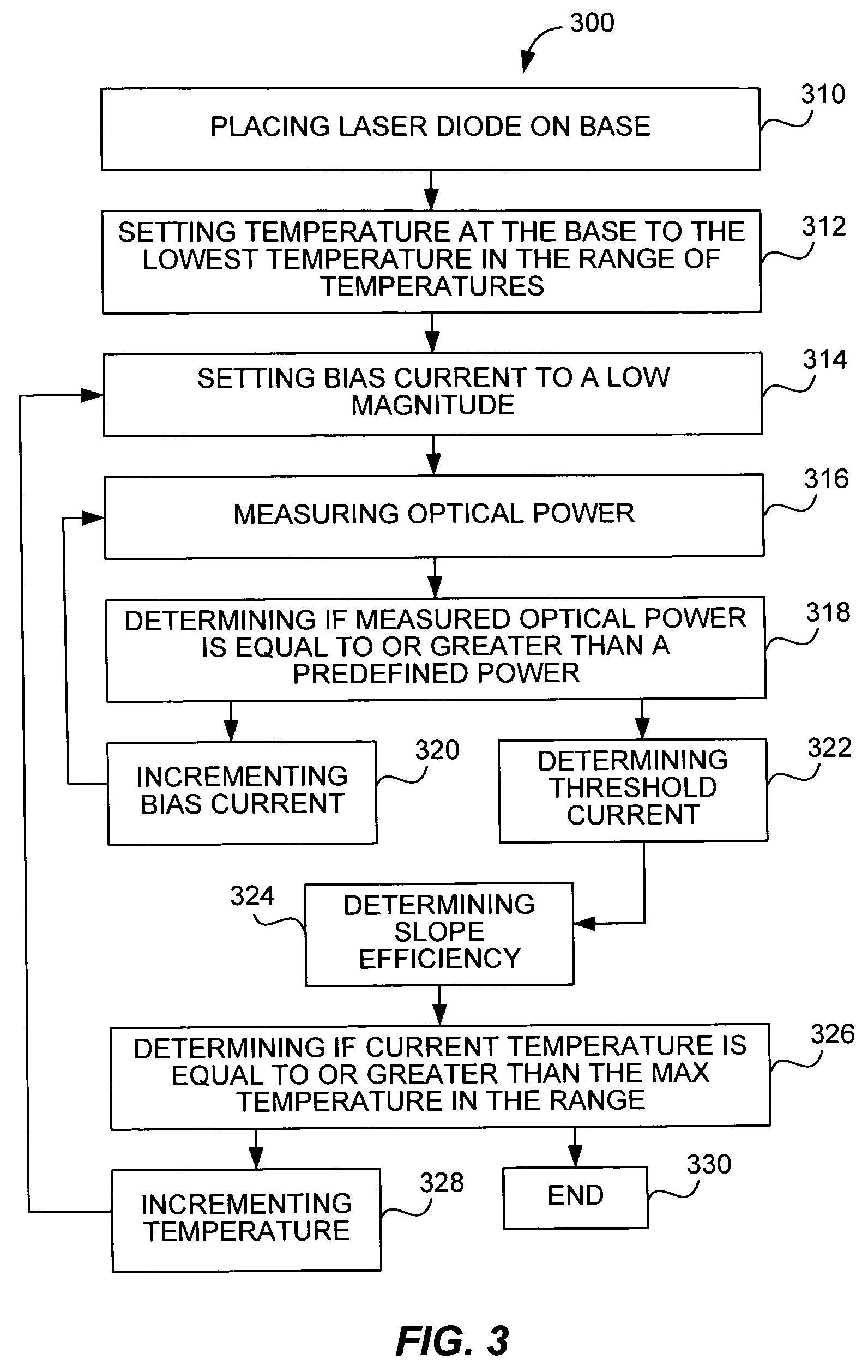
[0032] One aspect of the invention teaches methodologies for establishing a trim and compensation scheme for a laser device to be used in an optical link. In one aspect, a laser can be trimmed (i.e., set-up to have initial laser optical performance characteristics that fall within a pre-determined specification) using previously obtaining laser performance information in combination with a set of user specified performance parameters. In another aspect, the invention encompasses methodologies for determining and applying a temperature compensation scheme that c...


PUM


Abstract

A method includes a scheme for trimming and compensation for a laser emitter in a fiber optic link. Data models of laser performance are provided and used to determine a base power level. It is then confirmed that the base power level is satisfactory. If necessary, adjustments are made to a set of user specified performance parameters until a satisfactory base power level is obtained. Then a table or relation of temperatures and associated current and target average optical power values is generated such that they can be used to regulate laser emitter performance over a range of temperature. Additionally, fiber optic links capable of trimming and compensation are also disclosed.

Description

RELATED CASE [0001] The invention described herein is a continuation-in-part application claiming priority from the U.S. patent application Ser. No. 10 / 683,212, entitled “Laser Trim and Compensation Methodology for Passively Aligning Optical Transmitter”, invented by Wu and Deane. (Attorney Docket No. NSC1 P280 / P05697), and filed on Oct. 9, 2003. The aforementioned document is hereby incorporated by referenceTECHNICAL FIELD [0002] The invention described herein relates generally to laser diode control methods and apparatus for use in an optical transmission system. In particular, the invention relates to methods and structures for quickly trimming a laser transmitter and providing accurate temperature compensation for the transmitter. BACKGROUND [0003] Laser diodes are used in optical transmission systems as light emitters. FIG. 1 illustrates a conventional laser diode behavior. Conventional laser diodes generate a characteristic optical power curve 110, in which three ranges can be...

Claims


Application Information

Patent Timeline
IPC IPC(8): H01S3/00H01S5/00H01S5/06H01S5/068H04B10/155
CPCH01S5/0014H01S5/0617H04B10/564H01S5/06812H01S5/06804
Inventor WU, HSIN-HODEANE, PETER
Owner NAT SEMICON CORP
Why Eureka
Try Eureka