
Method and system for dynamically bounded spinning threads on a contested mutex

a dynamically bounded spinning thread and mutex technology, applied in the field of data processing system, can solve the problem of relatively significant overhead of thread suspension

Inactive Publication Date: 2005-04-14
IBM CORP
View PDF19 Cites 121 Cited by
  • Summary
  • Abstract
  • Description
  • Claims
  • Application Information

AI Technical Summary

Benefits of technology

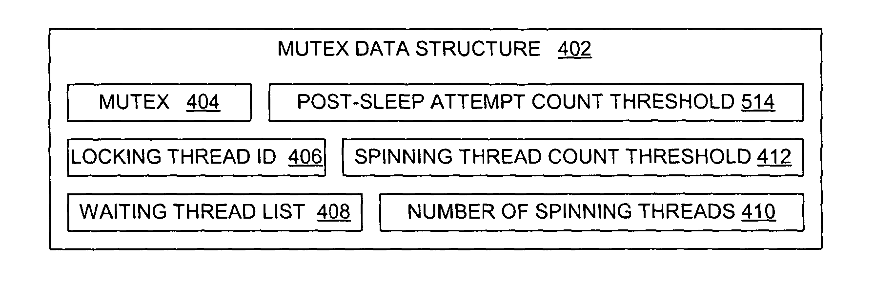
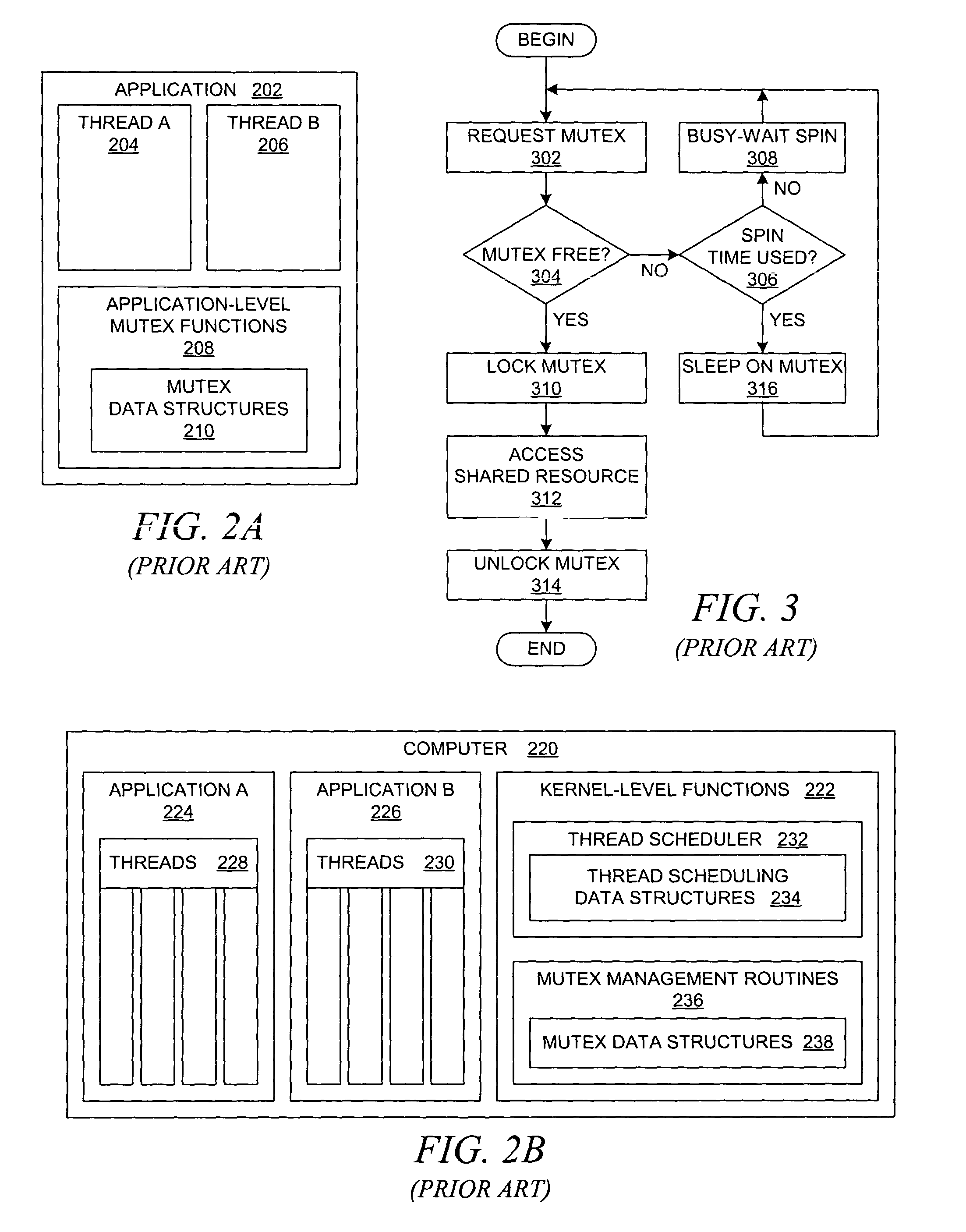
[0013] A method for managing a mutex in a data processing system is presented. For each mutex, a count is maintained of the number of threads that are spinning while waiting to acquire a mutex. If a thread attempts to acquire a locked mutex, then the thread enters a spin state or a sleep state based on restrictive conditions and the number of threads that are spinning during the attempted acquisition. In addition, the relative length of time that is required by a thread to spin on a mutex after already sleeping on the mutex may be used to regulate the number of threads that are allowed to spin on the mutex.

Problems solved by technology

Blocking quickly suspends the execution of a waiting thread, but the action of blocking may suspend a thread that would soon acquire the lock, and the suspension of a thread entails relatively significant overhead, e.g., the thread's execution context must be saved.

Method used


Image

  • Method and system for dynamically bounded spinning threads on a contested mutex
  • Method and system for dynamically bounded spinning threads on a contested mutex
  • Method and system for dynamically bounded spinning threads on a contested mutex

Examples


Embodiment Construction

[0027] In general, the devices that may comprise or relate to the present invention include a wide variety of data processing technology. Therefore, as background, a typical organization of hardware and software components within a distributed data processing system is described prior to describing the present invention in more detail.

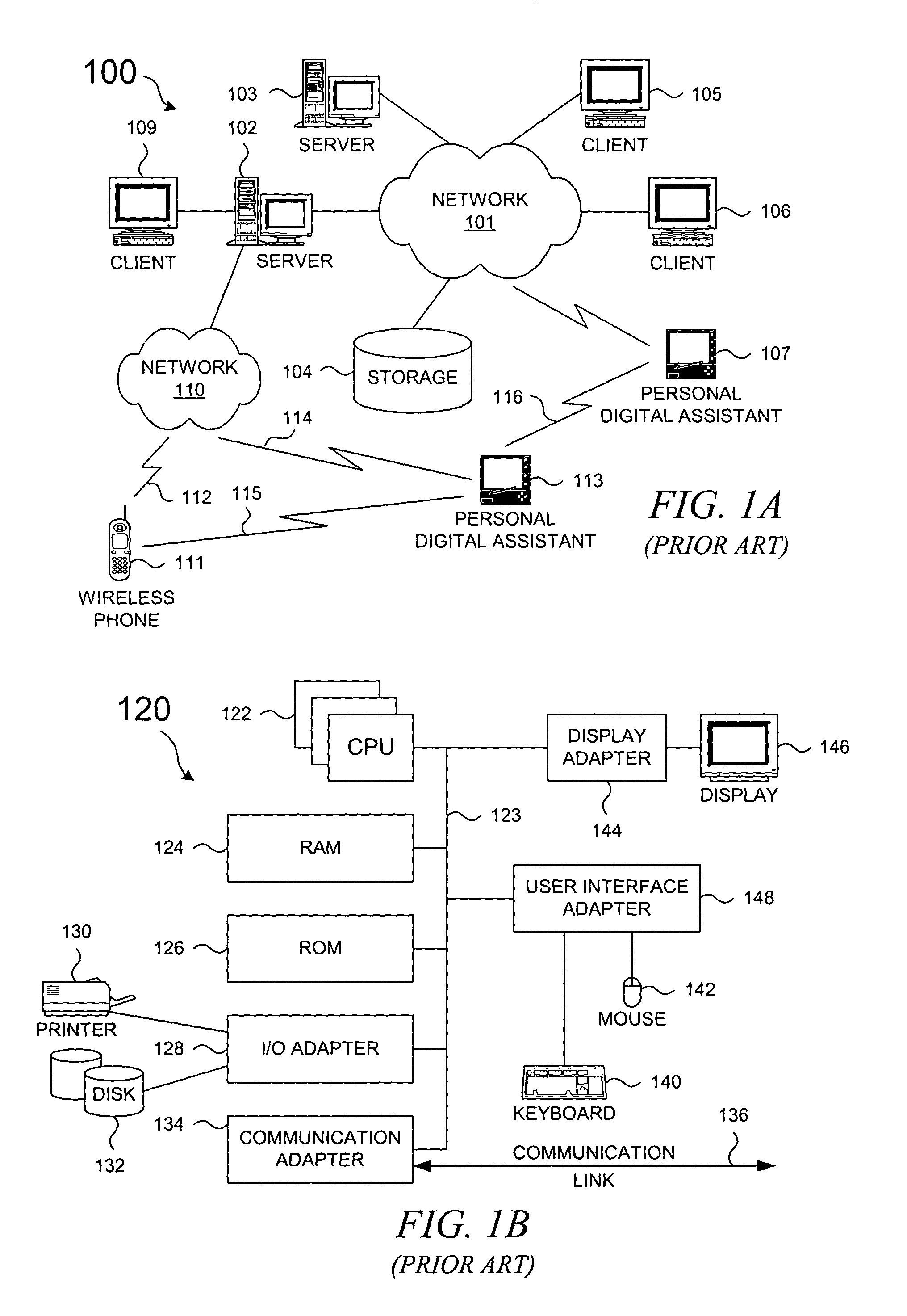
[0028] With reference now to the figures, FIG. 1A depicts a typical network of data processing systems, each of which may implement a portion of the present invention. Distributed data processing system 100 contains network 101, which is a medium that may be used to provide communications links between various devices and computers connected together within distributed data processing system 100. Network 101 may include permanent connections, such as wire or fiber optic cables, or temporary connections made through telephone or wireless communications. In the depicted example, server 102 and server 103 are connected to network 101 along with storage u...


PUM


Abstract

A method for managing a mutex in a data processing system is presented. For each mutex, a count is maintained of the number of threads that are spinning while waiting to acquire a mutex. If a thread attempts to acquire a locked mutex, then the thread enters a spin state or a sleep state based on restrictive conditions and the number of threads that are spinning during the attempted acquisition. In addition, the relative length of time that is required by a thread to spin on a mutex after already sleeping on the mutex may be used to regulate the number of threads that are allowed to spin on the mutex.

Description

BACKGROUND OF THE INVENTION [0001] 1. Field of the Invention [0002] The present invention relates to an improved data processing system and, in particular, to a method and apparatus for multiple process coordinating. Still more particularly, the present invention provides a method and apparatus for process scheduling or resource allocation during task management or control using mutual exclusion locks (mutexes). [0003] 2. Description of Related Art [0004] Modern operating systems support multiprogramming, whereby multiple programs appear to execute concurrently on a single computational device with a single central processing unit (CPU) or possibly multiple CPUs in a symmetric multiprocessor (SMP) machine. The appearance of concurrent execution is achieved through the use of serialized execution, also known as “time slicing”: the operating system of a device allows one of the multiple programs to execute exclusively for some limited period of time, i.e., a time slice, which is then ...

Claims


Application Information

Patent Timeline
Patent Type & Authority Applications(United States)
IPC IPC(8): G06F9/46G06F9/52
CPCG06F9/526
Inventor SCHOPP, JOEL HOWARD
Owner IBM CORP
Learn More