Liquid cooling device

a cooling device and liquid technology, applied in the direction of semiconductor/solid-state device details, lighting and heating apparatus, laminated elements, etc., can solve the problem of liquid not being able to flow in an optimized route in the casing to maximize heat exchange efficiency, and achieve the effect of maximizing heat exchange efficiency

Inactive Publication Date: 2005-04-21
HON HAI PRECISION IND CO LTD
View PDF12 Cites 43 Cited by
  • Summary
  • Abstract
  • Description
  • Claims
  • Application Information

AI Technical Summary

Benefits of technology

[0007] Accordingly, an object of the present invention is to provide a liquid cooling device getting improved liquid flow route for maximized heat exchange efficiency.

Problems solved by technology

As a result, the liquid is unable to flow in an optimized route in the casing to get maximized heat exchange efficiency, especially when the container is flat.

Method used


Image

  • Liquid cooling device
  • Liquid cooling device
  • Liquid cooling device

Examples


Embodiment Construction

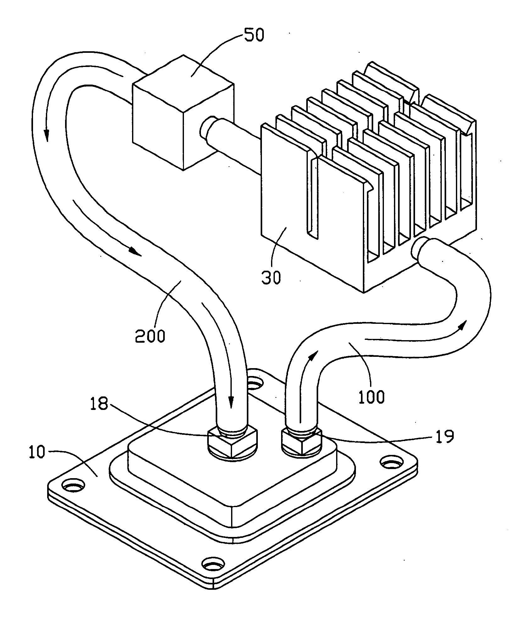
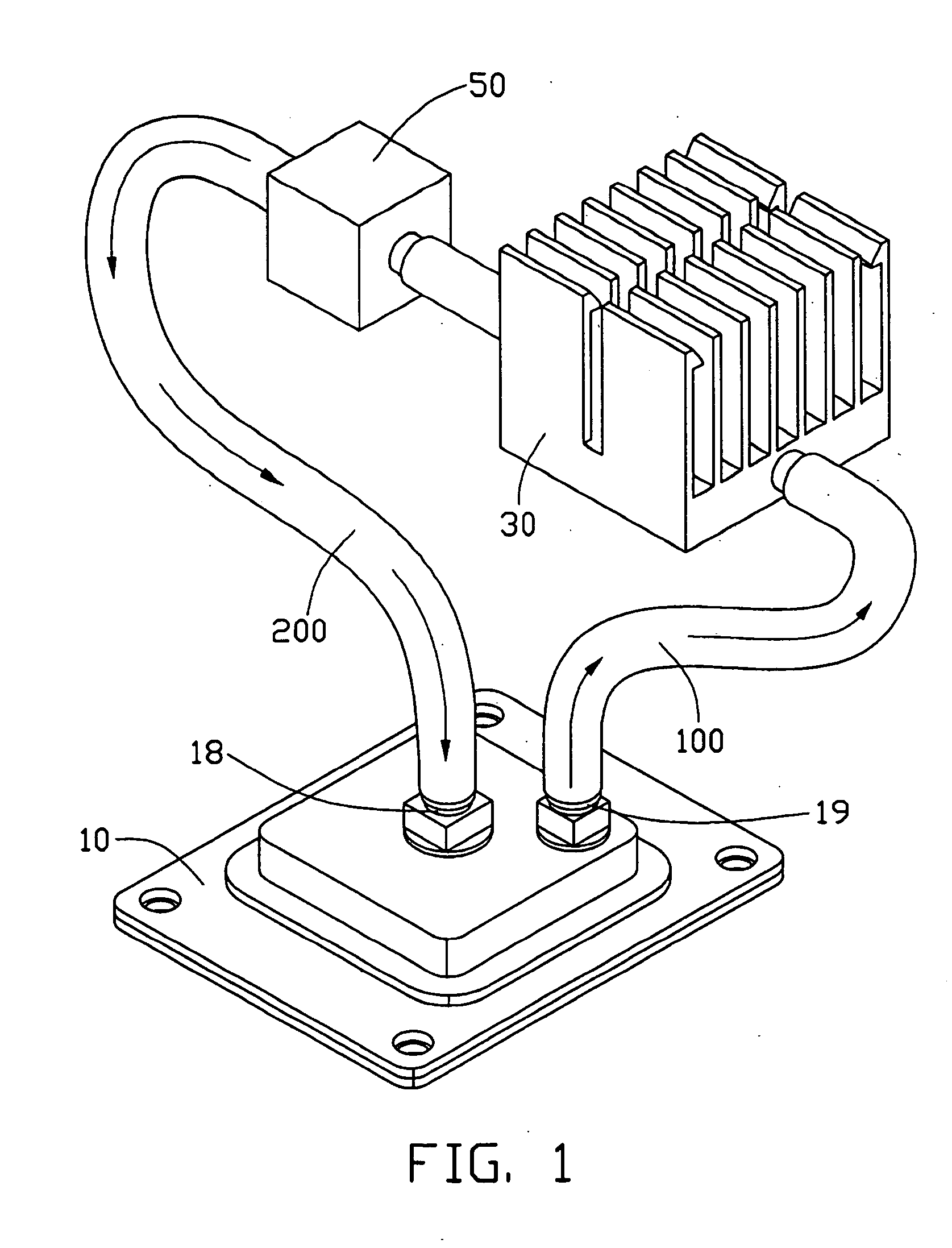
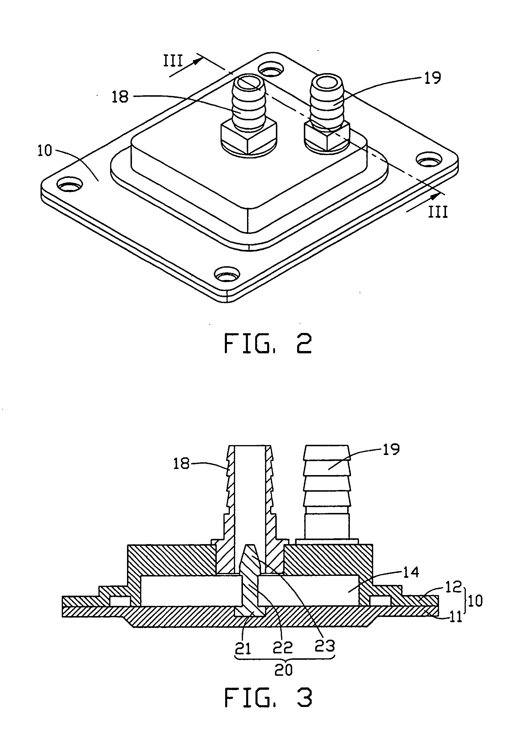
[0014] Referring to FIGS. 1-3, a liquid cooling device in accordance with the preferred embodiment of the present invention comprises a casing 10, and an actuator 50 connected to the casing 10 by a liquid outlet pipe 100 and a liquid inlet pipe 200 respectively at opposite locations of the actuator 50.

[0015] The casing 10 comprises a base 11 for intimately contacting a heat generating component or source (not shown) by a side surface thereof, and a lid 12 cooperating with the base 11 to form a container 14 therebetween to accommodate liquid for circulation. The base 11 and the lid 12 are hermetizated by calk packing, shim, or seal, for keeping the liquid from leaking out of the container 14. A pair of tubular connectors, for connecting the pipes 100, 200 to the casing 10, extends outwardly from the lid 12. The connectors are respectively named as liquid inlet port 18 and liquid outlet port 19, according to the directions along which the liquid flows in the connectors. The liquid in...


PUM


Abstract

A liquid cooling device includes a casing (10) having a container (14) for accommodating liquid therein, a liquid inlet port (18) in communication with the container, and a diversion member (20, 20′) located in the casing, for leading liquid from the liquid inlet port to a bottom of the container.

Description

BACKGROUND OF THE INVENTION [0001] 1. Field of the Invention [0002] The present invention relates to a cooling device, and more particularly to a cooling device for cooling a heat-generating device utilizing liquid. [0003] 2. Description of Related Art [0004] Liquid cooling devices were commonly utilized to cool huge systems such as furnaces. Today, liquid cooling devices also are used to cool electronic or electrical components, such as chipsets, dies or computer central processing units (CPUs), by circulating the cooling liquid in a channel. [0005] Generally, a liquid cooling device comprises a casing, forming a liquid container made of metal material. The casing comprises a base and a lid covering the base. The base is for contacting a cooled component. The lid comprises a liquid outlet and a liquid inlet Liquid pipes respectively connect the liquid outlet and the liquid inlet to a liquid tank. The liquid tank is further provided with a submersible motor therein. In operation to ...

Claims


Application Information

Patent Timeline
Patent Type & Authority Applications(United States)
IPC IPC(8): F28F27/02H01L23/473
CPCF28D15/00F28F3/12F28F9/0265H01L23/473H01L2924/0002H01L2924/00
Inventor LEE, HSIEH-KUNLAI, CHENG-TIENZHOU, SHI-WEN
Owner HON HAI PRECISION IND CO LTD
Why Eureka
Try Eureka