Heat exchanger

A heat exchanger and heat exchange tube technology, applied in heat exchange equipment, heat exchanger shells, lighting and heating equipment, etc., can solve the problems of heat exchange efficiency limitation, production efficiency reduction, high waste rate, etc., to reduce water pollution. Effect

Inactive Publication Date: 2014-02-19
YOO HAN
View PDF5 Cites 0 Cited by
  • Summary
  • Abstract
  • Description
  • Claims
  • Application Information

AI Technical Summary

Problems solved by technology

[0006] In other words, in the domestic patent application No. 10-2010-0019125, in terms of constituting the heat exchanger, the radiator, the oil cooler, the auxiliary water tank, and the condenser of the heating and cooling air conditioner are made of lightweight synthetic resin materials into two parts. The body can be welded and fixed, and the radiation fin can be firmly assembled to the heat sink junction of the body, so that low carbon can be discharged, the manufacturing process is simplified, the cost is reduced, the installation is easy, and the space occupation rate is minimized and proposed a heat exchanger with excellent heat dissipation, but in the above-mentioned prior application patent invention, the fluid channel through which the fluid passes is simply made into a tube body, so there is a limit when increasing the surface area for heat exchange, Therefore, the improvement of heat exchange efficiency is also limited
[0007] In addition, the whole body is welded after forming the front and rear two parts, so the welding surface is wide, and the synthetic resin liquid will flow down during the welding operation, so after welding and fixing the body, it is necessary to carry out post-processing, so there are the following: Problem: The manufacturing process is very cumbersome and reduces productivity
[0008] In addition, the welding surface is wide, so there are many difficulties in accurately welding and fixing it on the metal model, and the welding surface cannot be accurately welded and fixed, resulting in water leakage at the welding part, etc. The rejection rate of the product is high

Method used


Image

  • Heat exchanger
  • Heat exchanger
  • Heat exchanger

Examples


Embodiment Construction

[0032] Hereinafter, it will be described in detail in combination with preferred embodiments of the present invention and accompanying drawings.

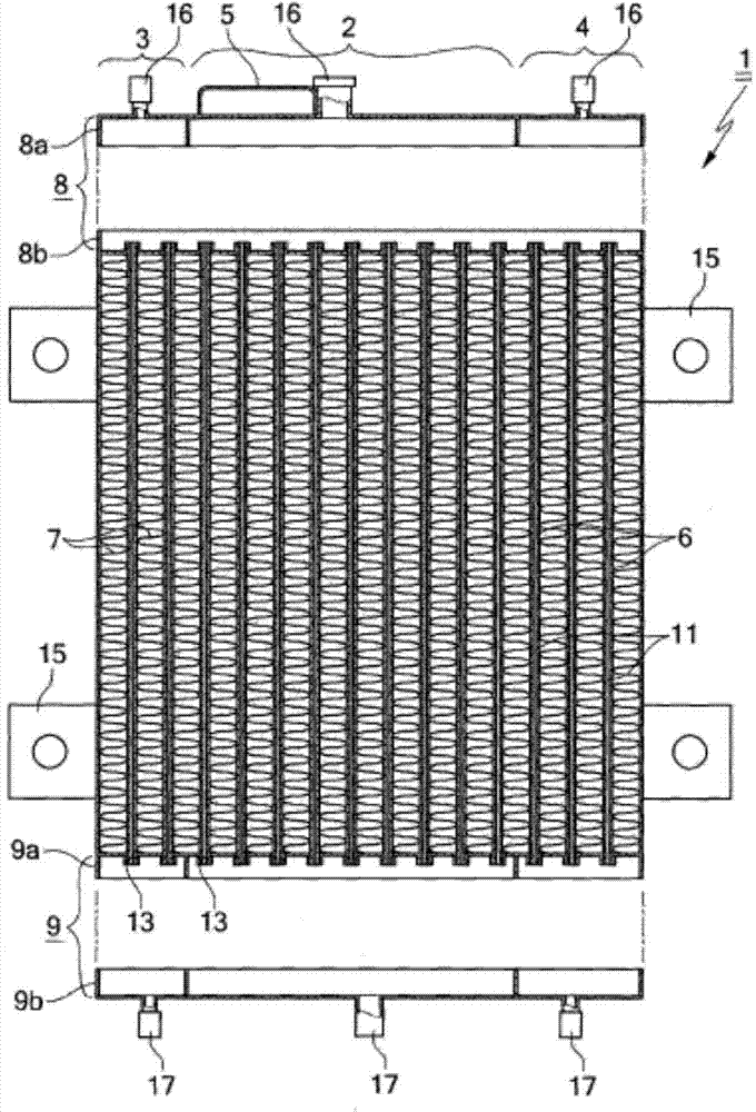
[0033] figure 1 It is a perspective view which shows a preferable example of the heat exchanger provided by this invention.

[0034] In other words, in the heat exchanger 1 of the present invention, the main body is injection-molded using a material such as nylon resin that has better heat dissipation than non-metallic aluminum.

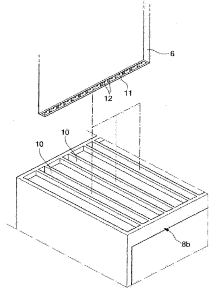
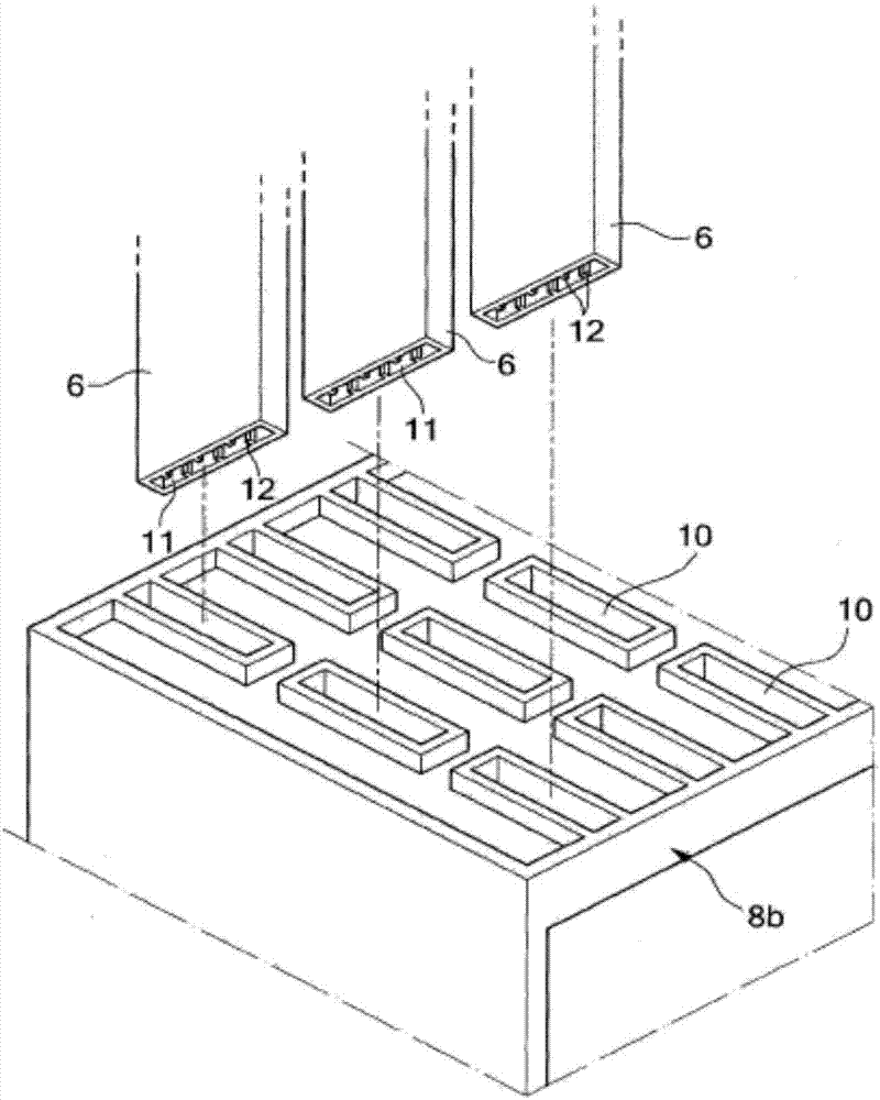
[0035] The above-mentioned heat exchanger 1 body includes: an upper body 8, which is injection-molded into a split type (split type); a lower body 9, which is additionally injection-molded; a plurality of heat exchange tubes 6, which are additionally extrusion-molded and other methods. Manufactured so as to be arranged between the upper body 8 and the lower body 9; a plurality of cooling fins 7 assembled between the above-mentioned heat exchange tubes 6 .

[0036] The above-mentioned upper body 8 is comp...


PUM


Abstract

PURPOSE: A heat exchanger is provided to minimize an error rate by securely assembling radiation fins to radiation pin joints of a main body and to reduce water contamination because lead is not required. CONSTITUTION: A heat exchanger comprises a main body. The main body is vertically divided into upper and lower bodies(8,9) and is horizontally divided into a radiator(2), an oil cooler(3), and a condenser(4). Heat exchanger pipes(6) are assembled to coupling holes formed on the upper and lower bodies. Radiation fins(7) are assembled between the heat exchange pipes. The radiator, the oil cooler, and the condenser have upper inlets(16) connected to fluid paths(11) of the heat exchange pipes and lower outlets(17).

Description

technical field [0001] The present invention relates to a heat exchanger, and more specifically relates to making a radiator (radiator), an oil cooler, a condenser for cooling and heating air conditioners, and an auxiliary water tank into a split type body using lightweight synthetic resin materials, thereby performing ( Heat, vibration) welded and fixed, and can improve heat exchange efficiency and maximize heat dissipation, and improve the convenience of manufacturing, the above-mentioned radiators and oil coolers, condensers for heating and cooling air conditioners, and auxiliary water tanks are used in automobiles and tractors , excavators, forklifts, etc., for cooling. Background technique [0002] Generally, in automobiles, tractors, excavators, forklifts, etc., in order to cool the high-temperature heat generated from the engine part and power steering oil, etc., cooling water and oil are circulated through radiators and oil coolers, etc. Wait for the same heat excha...

Claims


Application Information

Patent Timeline
Patent Type & Authority Applications(China)
IPC IPC(8): F28F9/18F28F9/013F28F19/02
CPCF28F1/40F28F9/013F28F9/187F28F21/06F28F2255/143
Inventor 朴涍汶
Owner YOO HAN
Why Eureka
Try Eureka