Heat exchanger

a heat exchanger and heat exchange medium technology, applied in indirect heat exchangers, lighting and heating apparatuses, laminated elements, etc., can solve the problems of complex installation structure of heat exchangers, inability to secure the heat transfer area increase the volume of heat exchangers, so as to achieve the maximum heat exchange efficiency between heating medium and combustion gas, reduce noise and vibration, and reduce the flow resistance of combustion gas

Active Publication Date: 2018-07-26
KYUNGDONG NAVIEN
View PDF0 Cites 0 Cited by
  • Summary
  • Abstract
  • Description
  • Claims
  • Application Information

AI Technical Summary

Benefits of technology

[0012]In accordance with a heat exchanger of the present invention, a heating medium flow channel and a combustion gas flow channel are formed inside a heat exchange unit configured by stacking a plurality of unit plates, an outer wall structure sealing an outer side surface through which a combustion gas passes is integrally formed therewith such that an installation structure of the heat exchanger can be simplified, and a plurality of combustion gas pass-through units are formed at a lower portion of a latent heat unit such that flow resistance of the combustion gas can be reduced and generation of noise and vibration can be minimized.
[0013]Further, a latent heat unit having multiple parallel heating medium flow channels and a sensible heat unit having serial heating medium flow channels are integrally formed by stacking a plurality of unit plates manufactured in a similar pattern, and thus a flow path of the heating medium is formed to be maximally long in a limited space such that heat exchange efficiency between the heating medium and the combustion gas can be maximized.

Problems solved by technology

However, in the conventional condensing type heat exchanger, there is a problem in that a volume of the heat exchanger is increased due to the blower being disposed above the housing and the structures of the sensible heat exchanger and the latent heat exchanger which are individually installed inside the housing.
The heat exchangers disclosed in the above-described patents each have a configuration in which an outer circumference of a helically wound heat exchange pipe is sealed to provide a flow channel of a combustion gas such that a housing should be separately provided, and thus an installation structure of the heat exchanger becomes complicated.
Further, the conventional heat exchanger has a structural limitation in that a flow path of the heating medium is short, and thus a heat transfer area between the heating medium and combustion gas cannot be widely secured.

Method used


Image

  • Heat exchanger
  • Heat exchanger
  • Heat exchanger

Examples


Embodiment Construction

[0034]Hereinafter, configurations and operations for preferred embodiments of the present disclosure will be described in detail with reference to the accompanying drawings.

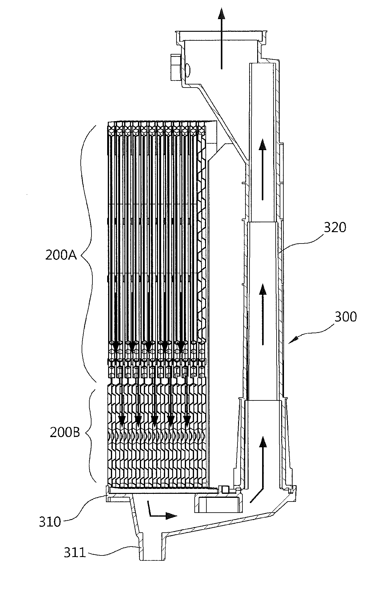
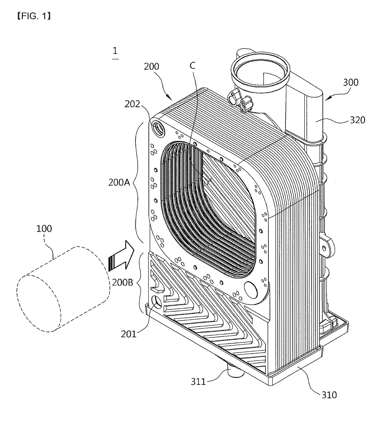
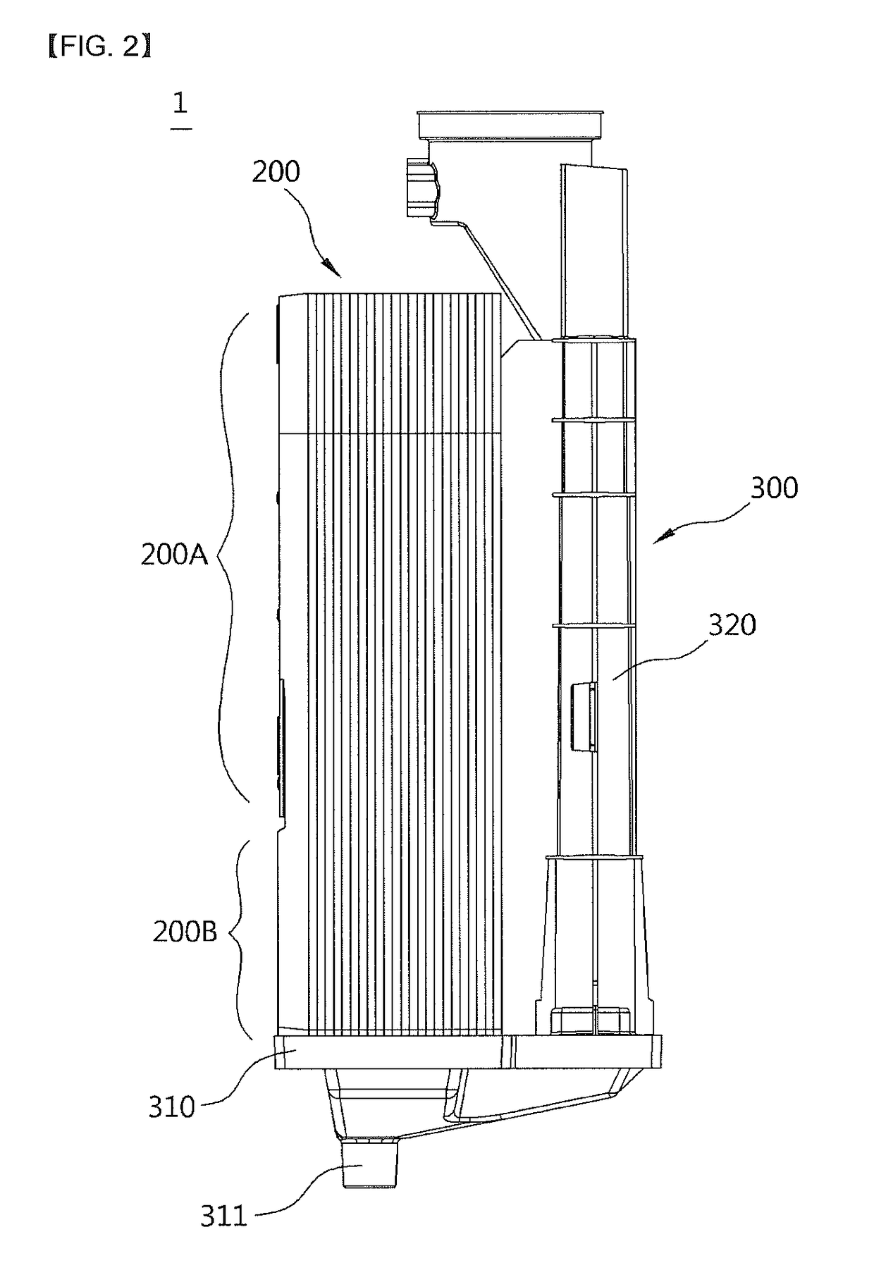
[0035]Referring to FIGS. 1 to 6, a heat exchanger 1 according to one embodiment of the present invention includes a burner 100 configured to burn a mixture of air and fuel to generate combustion heat and a combustion gas; a heat exchange unit 200 provided at a circumference of the burner 100 to perform a heat exchange between a heating medium and the combustion gas generated by combustion in the burner 100, and constituted by stacking a plurality of plates; and a combustion gas discharge unit 300 configured to discharge the combustion gas which passes through the heat exchange unit 200.

[0036]The burner 100 is a cylindrical burner and is assembled by being inserted into a space of a combustion chamber C provided at the heat exchange unit 200 in a horizontal direction from a front surface, thereby improving conveni...


PUM


Abstract

The present invention relates to a heat exchanger enabling the reduction of the number of components constituting the heat exchanger, the simplification of the coupling structure thereof, and also, the decrease of combustion gas flow resistance and the minimization of noise and vibration generation, the heat exchanger being provided with a heat exchange unit having heating medium flow channels through which a heating medium flows and combustion gas flow channels through which combustion gas combusted in the burner flows to be alternately formed and adjacent to each other in spaces between a plurality of plates, wherein the heat exchange unit comprises: a sensible heat unit which surrounds the outer side of a combustion chamber, is formed of one side area of the plates, and heats the heating medium by using sensible heat of combustion gas generated by the combustion of the burner; and a latent heat unit which is formed of the other side area of the plates, and heats the heating medium by using latent heat of water vapor included in combustion gas that has finished undergoing heat exchange in the sensible heat unit, wherein bent flange units are formed on the edges of the plurality of plates, and in a state where the flange units of neighboring plates overlap, certain areas among the edges of the plurality of plates have formed thereon combustion gas pass-through units having combustion gas flowing through the combustion gas flow channels pass therethrough.

Description

TECHNICAL FIELD[0001]The present invention relates to a heat exchanger, and more particularly, to a heat exchanger having a simplified assembly structure by stacking a plurality of plates to integrally form a sensible heat unit and a latent heat unit, and by integrally forming a case of the heat exchanger and a combustion gas pass-through unit using the stacked plates.BACKGROUND ART[0002]A boiler used for heating or warm water is a device configured to heat a desired area or supply warm water by heating water or direct water (hereinafter referred to as a “heating medium”) being heated by a heat source, and the boiler is configured to include a burner configured to combust a mixture of a gas and air and a heat exchanger configured to transfer combustion heat of a combustion gas to the heating medium.[0003]A boiler produced in an early stage uses a heat exchanger which heats a heating medium using only sensible heat generated when a burner performs a combustion operation, but a conden...

Claims


Application Information

Patent Timeline
Patent Type & Authority Applications(United States)
IPC IPC(8): F24H8/00F24H1/40F28D9/00F28F3/04F24H1/34
CPCF24H8/00F24H1/40F28D9/00F28F3/04F24H1/34F28D20/02F28D21/00F24H1/30F24H1/32F24H1/44F24H1/445F28F3/044F28F3/046F28D9/0043F28D9/005F28D9/0093F28D9/0037F28D21/0007F28D2021/0061Y02B30/00Y02E60/14
Inventor JEONG, INCHUL
Owner KYUNGDONG NAVIEN
Why Eureka
Try Eureka