Heat exchanger

a technology of heat exchanger and heat exchanger body, which is applied in the direction of indirect heat exchanger, lighting and heating apparatus, laminated elements, etc., can solve the problems of loss of heat, complex structure of heat exchanger, and increased so as to achieve the effect of reducing the flow resistance of heating medium, reducing the volume of heat exchanger, and reducing the heat insulating structure of combustion chamber

Active Publication Date: 2020-05-05
KYUNGDONG NAVIEN
View PDF18 Cites 0 Cited by
  • Summary
  • Abstract
  • Description
  • Claims
  • Application Information

AI Technical Summary

Benefits of technology

[0013]In accordance with a heat exchanger of the present invention, a connection flow channel of a heating medium is provided behind a sensible heat unit to direct a heating medium, which passes through a heating medium flow channel of a latent heat unit, to flow into a heating medium flow channel of the sensible heat unit, and a water housing cooling unit configured to heat-insulate a combustion chamber is provided such that a heat insulating structure of the combustion chamber can be simplified and flow resistance of the heating medium can also be reduced.
[0014]Further, a latent heat unit having multiple parallel heating medium flow channels and a sensible heat unit having serial heating medium flow channels are integrally formed by stacking a plurality of unit plates manufactured in a similar pattern, and thus a flow channel of the heating medium is formed to be maximally long in a limited space such that heat exchange efficiency between the heating medium and the combustion gas can be maximized.

Problems solved by technology

However, in the conventional condensing type heat exchanger, there is a problem in that a volume of the heat exchanger is increased due to the blower being disposed above the housing and the structures of the sensible heat exchanger and the latent heat exchanger which are individually installed inside the housing.
In each of the heat exchangers disclosed in the above-described patents, heat generated by combustion in the burner is transferred to an outer side of the combustion chamber and causes overheating of the heat exchanger, and thus heat insulating materials or heat radiating fins are additionally provided on an outer wall of the combustion chamber to prevent the heat transfer and the overheating such that there are problems in that a structure of the heat exchanger becomes complicated and a loss of heat occurs.
Further, the conventional heat exchanger has a structural limitation in that a flow channel of the heating medium is short, and thus a heat transfer area between the heating medium and combustion gas cannot be widely secured.

Method used


Image

  • Heat exchanger
  • Heat exchanger
  • Heat exchanger

Examples


Embodiment Construction

[0036]Hereinafter, configurations and operations for preferred embodiments of the present invention will be described in detail with reference to the accompanying drawings.

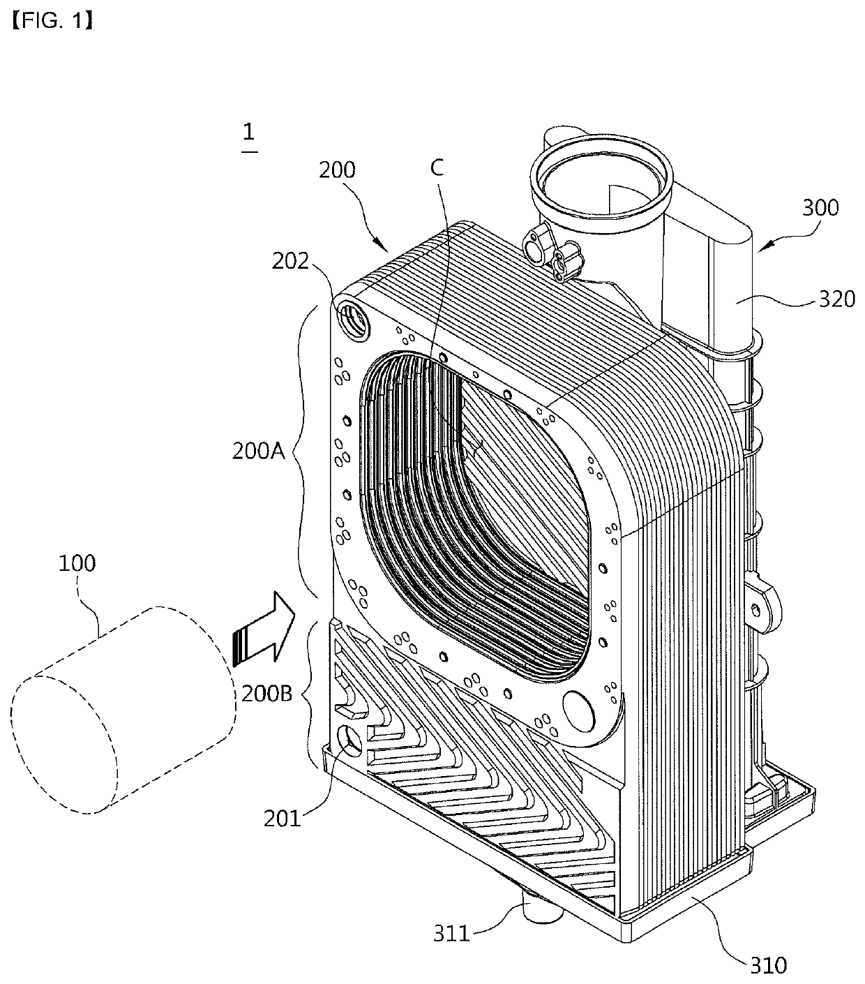
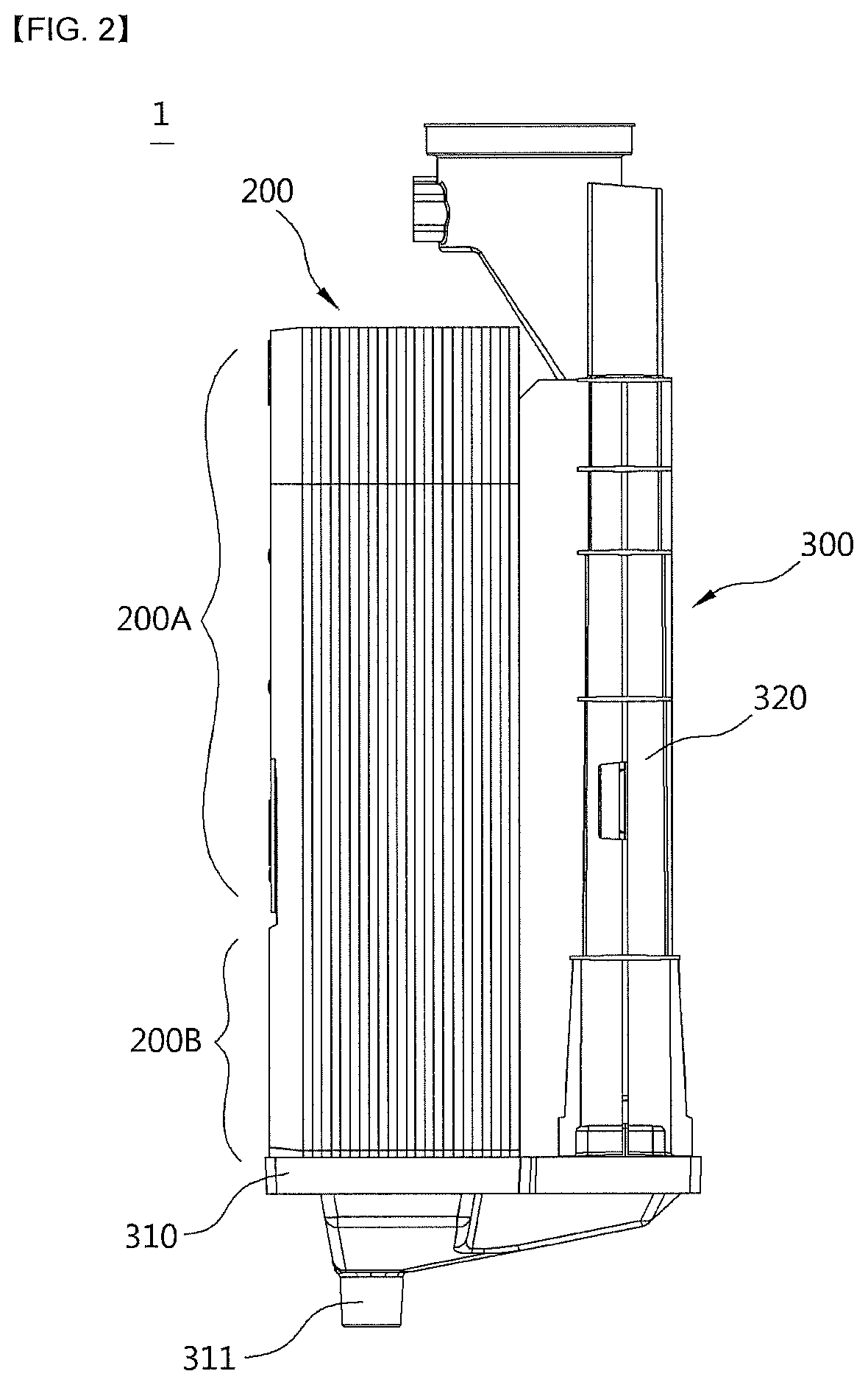
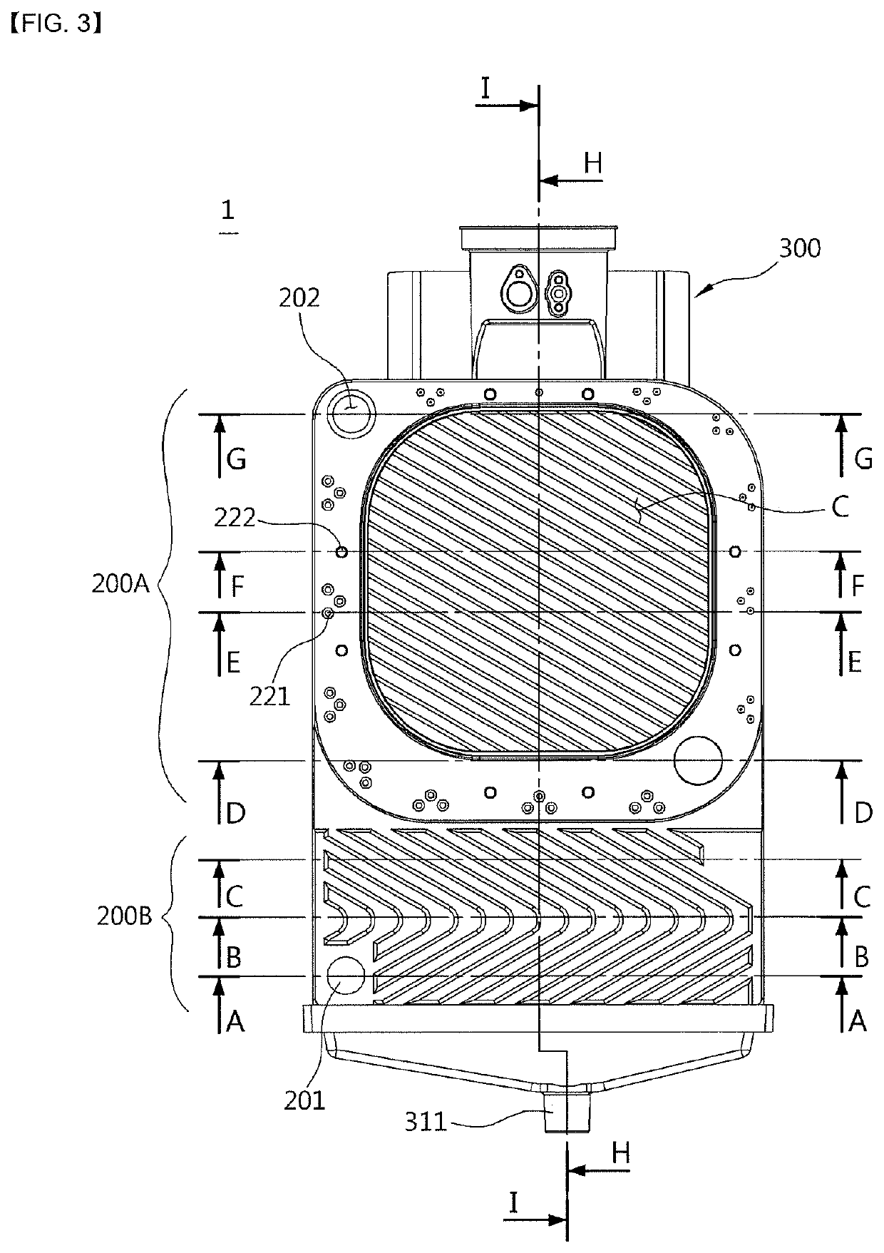
[0037]Referring to FIGS. 1 to 6, a heat exchanger 1 according to one embodiment of the present invention includes a burner 100 configured to combust a mixture of air and fuel to generate combustion heat and a combustion gas; a heat exchange unit 200 provided at a circumference of the burner 100 to perform a heat exchange between a heating medium and the combustion gas generated by the combustion in the burner 100, and constituted by stacking a plurality of plates; and a combustion gas discharge unit 300 configured to discharge a combustion gas which passes through the heat exchange unit 200.

[0038]The burner 100 is a cylindrical burner and is assembled by being inserted into a space of a combustion chamber C provided at the heat exchange unit 200 in a horizontal direction from a front surface, thereby improving con...


PUM


Abstract

The present invention relates to a heat exchanger having a simplified assembly structure as well as a simplified structure for heat-insulating a combustion chamber, the heat exchanger being provided with a heat exchange unit having heating medium flow channels through which a heating medium flows and combustion gas flow channels through which combustion gas combusted in the burner flows to be alternately formed and adjacent to each other in spaces between a plurality of plates, wherein the heat exchange unit comprises: a sensible heat unit which surrounds the outer side of a combustion chamber, is formed of one side area of the plates, and heats the heating medium by using sensible heat of combustion gas generated by the combustion of the burner; and a latent heat unit which is formed of the other side area of the plates, and heats the heating medium by using latent heat of water vapor included in combustion gas that has finished undergoing heat exchange in the sensible heat unit, wherein the rear of the sensible heat unit has provided thereon connection flow channels of the heating medium so that the heating medium that passed through the heating medium flow channels of the latent heat unit can flow to the heating medium flow channels of the sensible heat unit, and the rear of the sensible heat unit also has a water housing cooling unit formed thereon for heat-insulating the combustion chamber.

Description

CROSS-REFERENCE TO RELATED APPLICATIONS[0001]This application is a national stage of International Application No. PCT / KR2016 / 007716 filed Jul. 15, 2016, which claims the benefit of Korean Application No. 10-2015-0104096, filed Jul. 23, 2015, in the Korean Intellectual Property Office, the disclosure of which is incorporated herein in their entireties by reference.TECHNICAL FIELD[0002]The present invention relates to a heat exchanger, and more particularly, to a heat exchanger having a simplified structure for heat-insulating a combustion chamber and a simplified assembly structure by stacking a plurality of plates to integrally form a sensible heat unit and a latent heat unit.BACKGROUND ART[0003]A boiler used for heating or warm water is a device configured to heat a desired area or supply warm water by heating water or direct water (hereinafter referred to as a “heating medium”) being heated by a heat source, and the boiler is configured to include a burner configured to combust a...

Claims


Application Information

Patent Timeline
Patent Type & Authority Patents(United States)
IPC IPC(8): F24H8/00F24H1/30F24H1/40F28F3/04F24H1/34F28D9/00F24H1/44F24H1/32F28D21/00
CPCF24H8/00F24H1/30F24H1/40F24H1/32F28F3/04F28D9/00F24H1/445F24H1/34F28D9/0043F24H1/44F28D9/005F28D2021/0024Y02B30/102Y02B30/00
Inventor JEONG, INCHUL
Owner KYUNGDONG NAVIEN
Why Eureka
Try Eureka