Road safety warning system and method

a technology of road safety and warning system, applied in the field of road safety warning system, can solve problems such as significant modifications to existing infrastructur

Inactive Publication Date: 2005-04-21
SHIRI YOSSEF
View PDF4 Cites 68 Cited by
  • Summary
  • Abstract
  • Description
  • Claims
  • Application Information

AI Technical Summary

Benefits of technology

[0009] It is a particular object of the invention to provide an in-vehicle system for tracking road signs and alert

Problems solved by technology

Such sensors may be used to convey to the motorist information relating to traffic signs, such as STOP, but this req

Method used


Image

  • Road safety warning system and method
  • Road safety warning system and method
  • Road safety warning system and method

Examples


Embodiment Construction

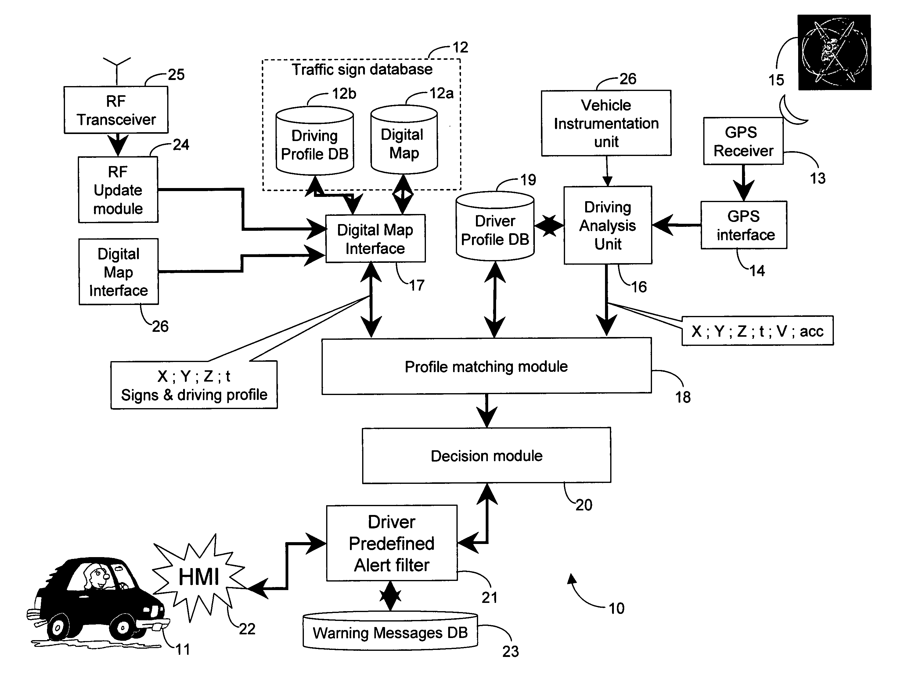
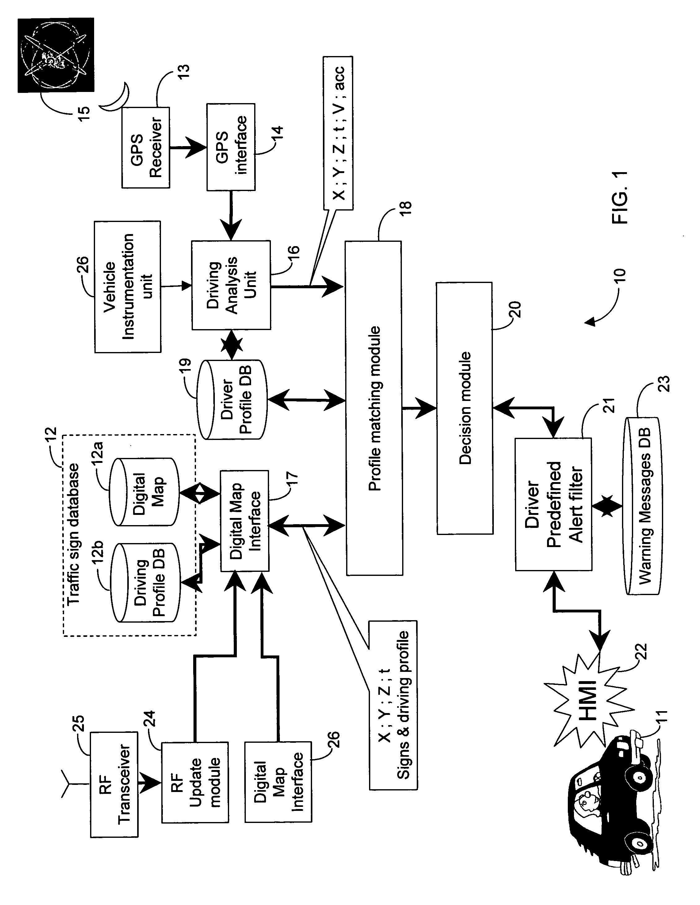
[0026]FIG. 1 shows functionally an in-vehicle road safety system 10 according to the invention that is mounted inside a vehicle 11 for tracking traffic signs and alerting a motorist of the vehicle 11 of an impending significant traffic sign. The system 10 comprises a digital map database 12 a mapping traffic signs according to their location in 3-D space. The traffic signs constitute events that occur at specific locations of a transportation route and in connection with which a driver of the vehicle may need to be forewarned. The digital map database stores (x, y, z, t) coordinates of traffic signs so as to indicate spatial and time coordinates associated therewith. The time coordinates (t) indicate any time restrictions associated with the respective traffic sign. For example, a speed limitation or a direction limitation, such as no right turn, may be effective only during certain hours of the day. Also associated with the digital map database 12a is a driving profile database 12b...


PUM


Abstract

An in-vehicle system for tracking events that occur at specific locations of a transportation route and alerting a driver of an impending significant event includes a location determination unit for determining an instantaneous location of the vehicle, and an event determination unit coupled to the location determination unit and responsive to the instantaneous location of the vehicle for communicating with an events database for obtaining an impending traffic sign that the vehicle is about to confront based on the vehicle's instantaneous location. A decision module coupled to the event determination unit is responsive to current parameters of the vehicle for determining whether the current parameters of the vehicle are conducive to safe driving based on the impending event, and a warning unit coupled to the decision module is responsive to at least one current parameter of the vehicle not being conducive to safe driving for alerting the driver of the impending event.

Description

FIELD OF THE INVENTION [0001] This invention relates to road safety warning systems. BACKGROUND OF THE INVENTION [0002] Various attempts have been made in the art to address the need to provide motorists with advance information relating to hazardous road conditions in order to permit them to take defensive action and avoid accidents. [0003] For example, U.S. Pat. No. 6,487,500 (Lemelson et al) issued Nov. 26, 2002 entitled “GPS vehicle collision avoidance warning and control system and method” discloses a GPS based location system that continuously determines a vehicle's tracking position on a pathway with centimeter accuracy. The GPS-based position is communicated with selected other status information to other vehicles in the vicinity, to a station and / or to one of a plurality of control centers, which relay to the vehicle each of the other vehicles' status information and kinematic tracking position. Objects are detected from all directions by various sensors and data are comput...

Claims


Application Information

Patent Timeline
IPC IPC(8): G08G1/0962
CPCG01C21/3697G08G1/0962
Inventor SHAFIR, MICHAELSHIRI, YOSEF
Owner SHIRI YOSSEF
Why Eureka
Try Eureka