Plasma display panel device using sub-field mode and method of driving the same

a display panel and sub-field technology, applied in the field of pdp devices using sub-field modes and driving pdp devices, can solve the problems of inability to obtain linear gray level with respect to image signal, inability to perform smooth gray scale representation on the screen, etc., and achieve the effect of ensuring the linearity of gray level

Inactive Publication Date: 2005-04-21
SAMSUNG ELECTRONICS CO LTD
View PDF6 Cites 6 Cited by
  • Summary
  • Abstract
  • Description
  • Claims
  • Application Information

AI Technical Summary

Benefits of technology

[0018] The present invention provides a plasma display panel (PDP) device using a sub-field m

Problems solved by technology

That is, according to the conventional sub-field method, since a sustain pulse of an even number cannot be represented, the linearity of the

Method used


Image

  • Plasma display panel device using sub-field mode and method of driving the same
  • Plasma display panel device using sub-field mode and method of driving the same
  • Plasma display panel device using sub-field mode and method of driving the same

Examples


Embodiment Construction

[0039] Hereinafter, an exemplary embodiment of the present invention will be described in detail with reference to the accompanying drawings.

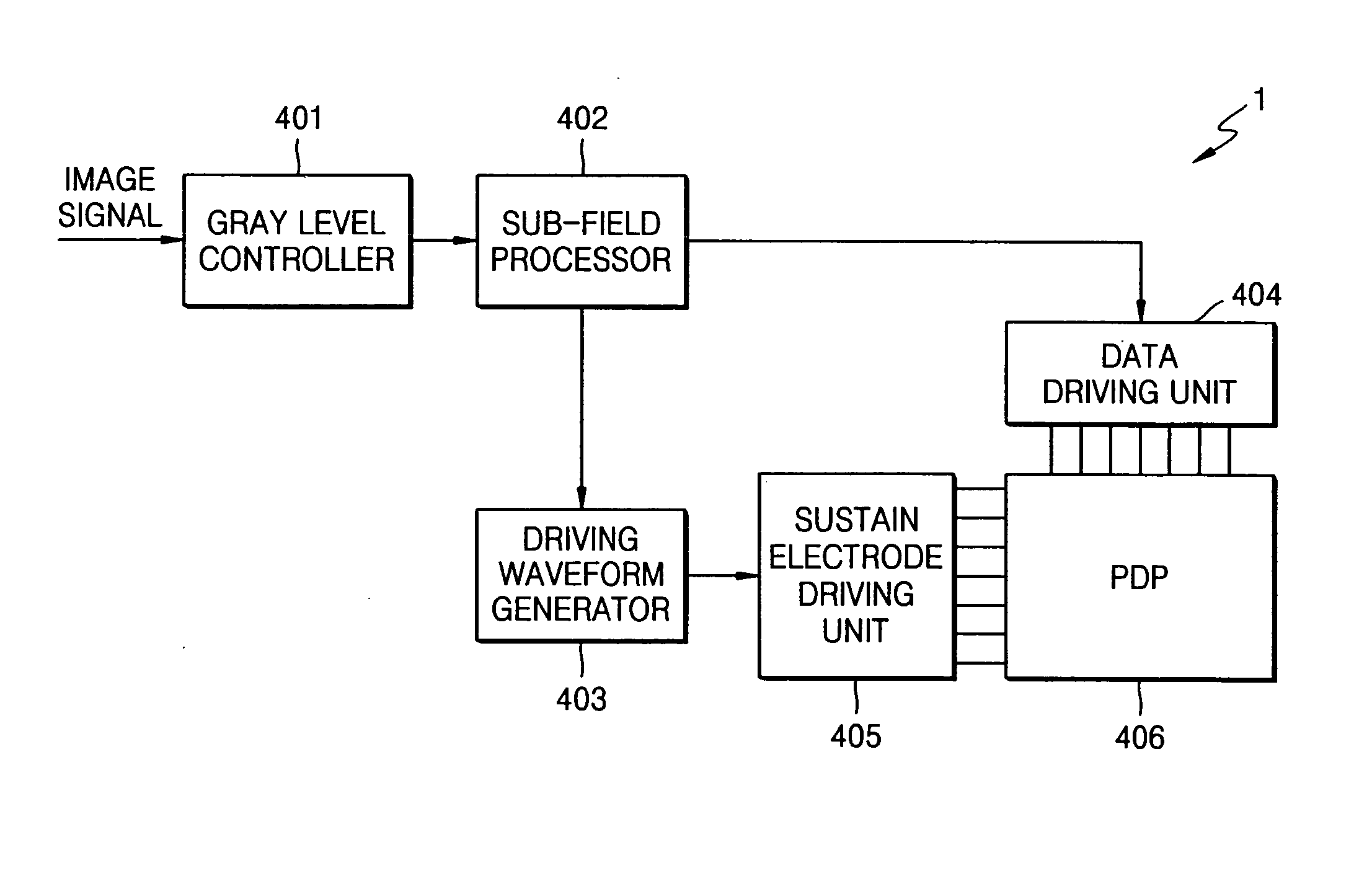
[0040]FIG. 4 is a block diagram of a plasma display panel (PDP) device 1 according to an exemplary embodiment of the present invention.

[0041] Referring to FIG. 4, the PDP device 1 includes a gray level controller 401, a sub-field processor 402, a driving waveform generator 403, a data driving unit 404, a sustain electrode driving unit 405, and a PDP 406.

[0042] The gray level controller 401 receives an image signal, sets an appropriate gray level that represents brightness of a pixel in response to the received image signal, selects appropriate sub-fields for implementing the set gray level, and transmits information regarding the sub-field selection to the sub-field processor 402.

[0043] The sub-field processor 402 receives the information regarding the sub-field selection from the gray level controller 401 and generates a conversion timing ...


PUM


Abstract

Provided are a plasma display panel (PDP) device using a sub-field mode and a method of driving the PDP device. The method of driving the PDP includes allocating a first event pulse for generating an even number of light pulses or a second event pulse for generating an odd number of light pulses to each sub-field, and outputting sustain pulses, which generate light pulses, according to the allocated event pulse. Thus, linearity of the gray level can be improved and an image quality can be improved.

Description

BACKGROUND OF THE INVENTION [0001] This application claims priority from Korean Patent Application No. 2003-58245, filed on Aug. 22, 2003, in the Korean Intellectual Property Office, the disclosure of which is incorporated herein in its entirety by reference. [0002] 1. Field of the Invention [0003] The present invention relates to a plasma display panel (PDP) device, and more particularly, to a PDP device using a sub-field mode and a method of driving the PDP device. [0004] 2. Description of the Related Art [0005] A plasma display panel (PDP) is a flat panel display device in which light is emitted by injecting mixed gas between two thin glass substrates, thereby applying a voltage therebetween. More specifically, an electric potential difference of pulse shape is formed between an A(address) electrode and a Y sustain electrode and discharged, a discharge of an X sustain electrode into the Y sustain electrode is induced, and phosphors of red (R), green (G), and blue (B) colors are e...

Claims


Application Information

Patent Timeline
IPC IPC(8): G09F9/313H04N5/66G09G3/20G09G3/28G09G3/288G09G3/291G09G3/294G09G3/298H01J17/49
CPCG09G3/2803G09G3/294G09G2320/066G09G2320/0271G09G3/2946G09G3/291G09G3/296
Inventor ROH, CHUNG-WOOKKIM, YOUNG-SUNKIM, HYE-JEONG
Owner SAMSUNG ELECTRONICS CO LTD
Why Eureka
Try Eureka