
Reciprocating pump

Inactive Publication Date: 2020-04-02
IWAKI
View PDF3 Cites 2 Cited by
  • Summary
  • Abstract
  • Description
  • Claims
  • Application Information

AI Technical Summary

Benefits of technology

The present invention ensures that a discharge operation occurs in a linear manner, which allows for low-speed operation with less air. This reduces the negative pressure and load on a diaphragm when performing a sucking operation.

Problems solved by technology

Therefore, a complicated control or structure is required to discharge a liquid of a constant amount or a constant pressure.
In this case, however, a device which generates a negative pressure is required in a sucking step.
In the case where an ejector is used, it is necessary to continuously discharge air during the sucking operation and hence, a consumption amount of air is increased.
When the diaphragm is always biased in one direction by a spring back method, a differential pressure is generated between the front and rear of the diaphragm so that there is a problem that the diaphragm is required to have a high strength.
Further, in the case of the spring back method, a suction time (suction force) cannot be adjusted and hence, it is difficult to perform a low speed operation, thus having a problem that a transfer liquid generates foam or cannot be sucked.

Method used


Image

  • Reciprocating pump
  • Reciprocating pump
  • Reciprocating pump

Examples


Embodiment Construction

[0017]Hereinafter, a reciprocating pump according to an embodiment of the present invention is described in detail with reference to attached drawings. However, the embodiment described hereinafter does not limit the invention according to respective claims. Further, it is not necessarily the case that all combinations of features described in the embodiment are indispensable as a solving means of the invention.

[Configuration of Liquid Feed System]

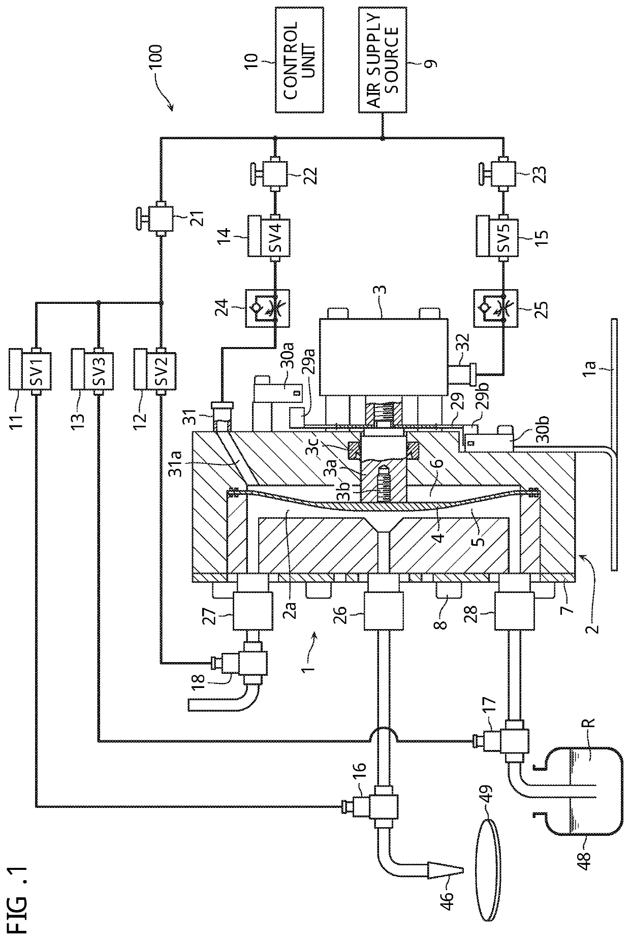
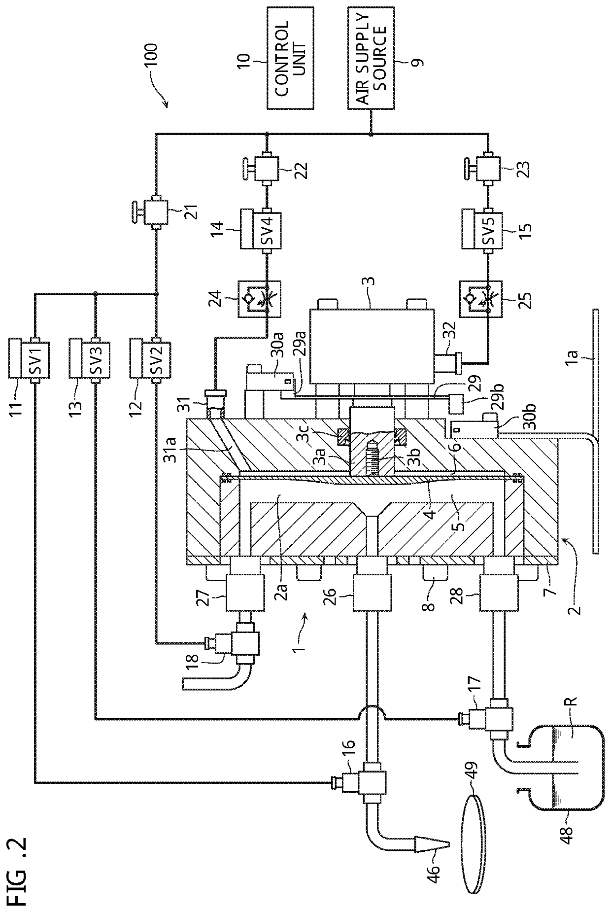
[0018]As shown in FIG. 1 and FIG. 2, a liquid feed system 100 includes a metering pump 1 as a reciprocating pump according to this embodiment, and a control unit 10 which controls the operation of the entire metering pump 1. The metering pump 1 includes a pump head 2 and an air cylinder 3 as a driving means which is mounted on the back surface side of the pump head 2.

[0019]The metering pump 1 of this embodiment feeds a resist R to be applied by coating to the upper surface of a semiconductor wafer 49 as a transfer fluid, for example. Howev...


PUM


Abstract

A reciprocating pump includes: a pump head having an inner space; a diaphragm configured to partition the inner space of the pump head into a pump chamber into which a transfer fluid is to be introduced and a working chamber into which working air is to be introduced; a driving device including a reciprocating member coupled to the diaphragm, the driving device being capable of driving the reciprocating member with the working air at least in a direction that the diaphragm is retracted; and a working air switching device.

Description

CROSS-REFERENCE TO RELATED APPLICATIONS[0001]This application is based upon and claims the benefit of priority from the prior Japanese Patent Application No. 2018-182025, filed on Sep. 27, 2018, the entire contents of which are incorporated herein by reference.BACKGROUND OF THE INVENTIONField of the Invention[0002]The present invention relates to a reciprocating pump.Description of the Related Art[0003]A reciprocating pump is known which causes a diaphragm to reciprocate. For example, as one example of the reciprocating pump, a resist pump is known which is used in applying a resist by coating to the upper surface of a semiconductor wafer by a spin coating method at a former stage in a step of exposing the semiconductor wafer (see Japanese Patent Laid-Open No. 2006-352002, for example). To prevent the generation of air bubbles, this resist pump is configured such that the discharge amount of a resist is set larger than that in a pump which feeds a resist to a nozzle at a constant fl...

Claims


Application Information

Patent Timeline
IPC IPC(8): F04B43/067F04B43/073F04B49/22F04B53/06H01L21/67
CPCF04B49/22F04B53/06F04B43/0733F04B53/16H01L21/67023F04B43/067F04B43/073H01L21/67017F04B43/06F04B53/10F04B53/14F05B2210/11
Inventor MATSUO, SHIGEYOSHITANABE, HIROYUKITANAKA, MOTOHIRO
Owner IWAKI
Learn More