
Ceiling fan motor

a fan motor and fan body technology, applied in the direction of dynamo-electric machines, structural associations, supports/encloses/casings, etc., can solve the problems of high energy consumption, low efficiency, unstable operation at low speeds, and complex configuration of the rotator in single-phase ac induction motors, so as to achieve low energy consumption, high stability of operation, and low noise

Active Publication Date: 2010-07-13
ZHONGSHAN BROAD OCEAN
View PDF5 Cites 1 Cited by
  • Summary
  • Abstract
  • Description
  • Claims
  • Application Information

AI Technical Summary

Benefits of technology

[0006]Therefore, it is one objective of the invention to provide a ceiling fan motor having low energy consumption, low noise, high stability of operation at low speeds, simple structure, and easy assembly.
[0015]As a result, the ceiling fan motor of the invention provides the following advantages: 1) Since the motor adopts brushless DC external rotor motor, it is energy efficient, produces low noise, and can operate stably at low speeds; and 2) The rotator has a simple structure, is easy to assemble, and has a low cost.

Problems solved by technology

Conventional ceiling fans employ single-phase AC induction motors characterized by high energy consumption, low efficiency, booming noise, and unstable operation at low speeds.
In addition, the configuration of the rotator in single-phase AC induction motors is complicated, the assembly difficult, and the cost high.

Method used


Image

  • Ceiling fan motor
  • Ceiling fan motor
  • Ceiling fan motor

Examples


Embodiment Construction

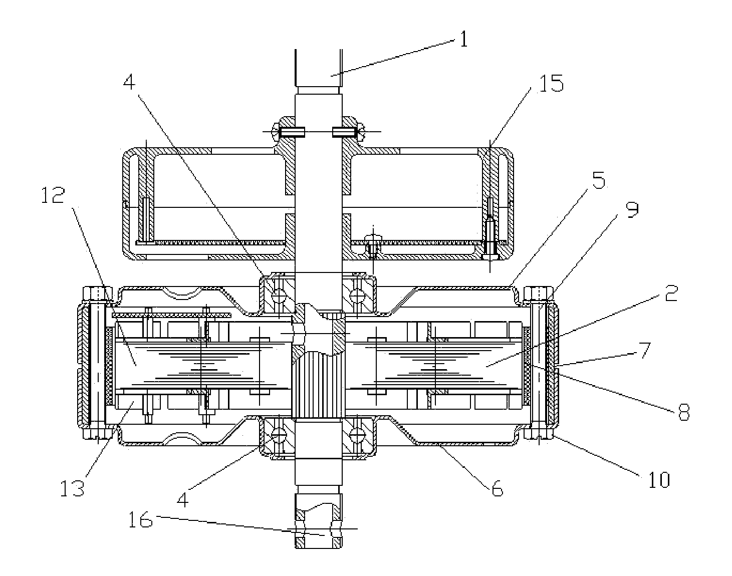
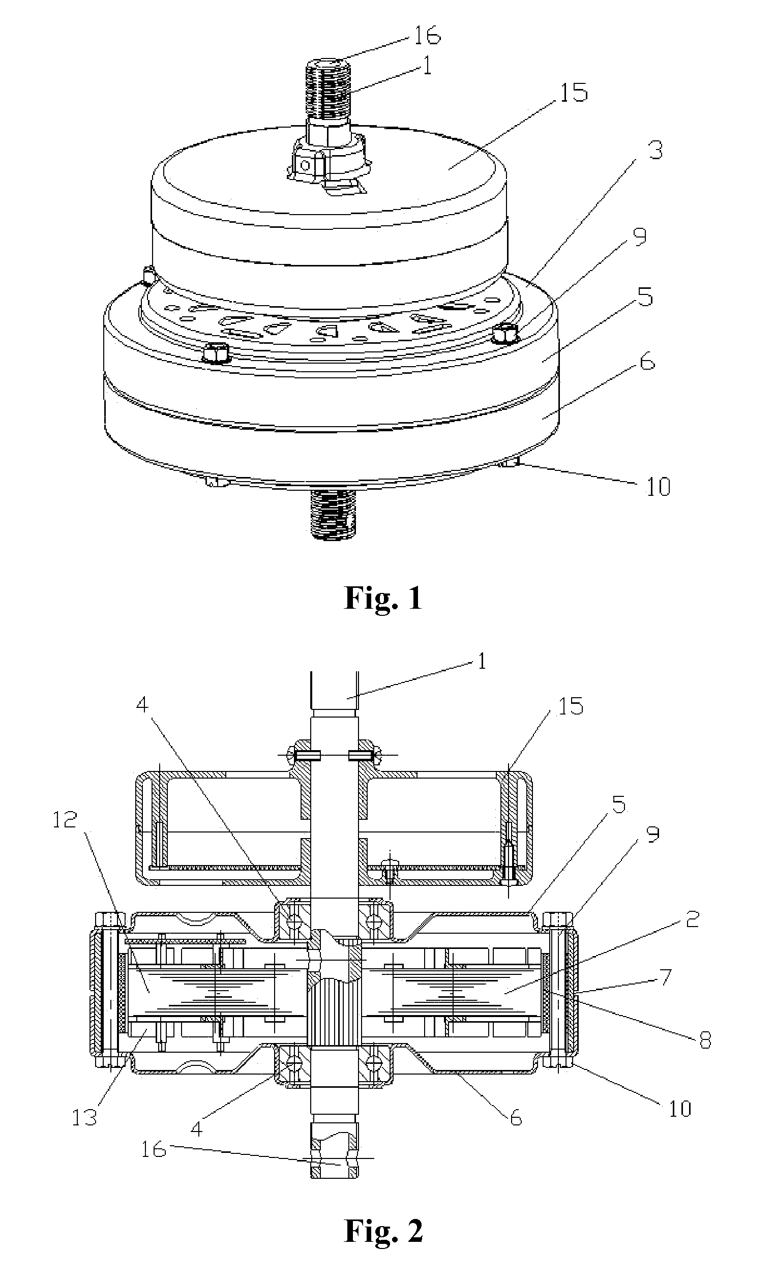
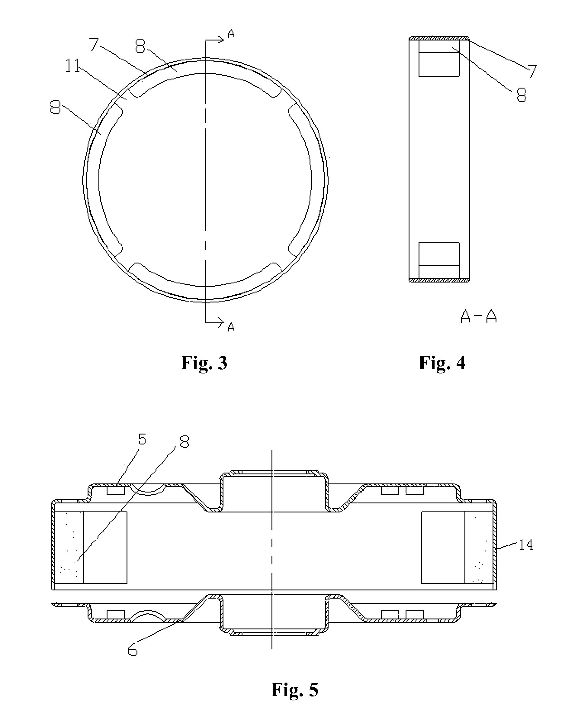
[0023]As shown in FIGS. 1-4, the ceiling fan motor of the invention is a brushless DC external rotor motor. The motor comprises an electrical control member and a motor structural member. The motor structural member comprises a shaft 1, a stator 2, and a rotator 3. The stator is fit over the shaft 1. The rotator 3 is fit over the stator 2. The stator 3 is engaged with the shaft 1 via a pair of bearings 4. The rotator 3 comprises a top end cover 5, a bottom end cover 6, an outer shell cover ring 7, and a plurality of magnets 8. The magnets 8 are positioned along the circumferential direction of the inner wall of the outer shell cover ring 7. The top end cover 5 and the bottom end cover 6 are installed on the top and the bottom of the cover ring 7, respectively, and are connected to each other by means of a plurality of bolts 9 and nuts 10. A gap 11 is disposed between the two adjacent magnets on the inner wall of the outer shell cover ring 7, and serves for the passage of the bolt 9....


PUM


Abstract

The invention teaches a ceiling fan motor, and specifically, a brushless DC external rotor motor, comprising an electrical control member and a motor structural member, wherein the motor structural member comprises a shaft 1, a stator 2, and a rotator 3, the stator is fit over the shaft 1, the rotator is fit over the stator 2, and the stator 3 is engaged with the shaft 1 via a pair of bearings 4. The rotator 3 comprises a top end cover 5, a bottom end cover 6, an outer shell cover ring 7, and a plurality of magnets 8, wherein the magnets 8 are positioned along the circumferential direction of the inner wall of the outer shell cover ring 7. The top end cover 5 and the bottom end cover 6 are installed on the top and bottom of the cover ring 7, respectively, and are connected to each other by means of a plurality of bolts and nuts. The ceiling fan motor of the invention provides the advantages of efficient energy consumption, low noise, and high operational stability at low speeds.

Description

CROSS-REFERENCE TO RELATED APPLICATIONS[0001]Pursuant to 35 U.S.C. §119 and the Paris Convention Treaty, this application claims the benefit of Chinese Patent Application No. 200620061702.1 filed Jul. 11, 2006, the contents of which are incorporated herein by reference.BACKGROUND OF THE INVENTION[0002]1. Field of the Invention[0003]The invention relates to electric motors, and more particularly to ceiling fan motors.[0004]2. Description of the Related Art[0005]Conventional ceiling fans employ single-phase AC induction motors characterized by high energy consumption, low efficiency, booming noise, and unstable operation at low speeds. In addition, the configuration of the rotator in single-phase AC induction motors is complicated, the assembly difficult, and the cost high.SUMMARY OF THE INVENTION[0006]Therefore, it is one objective of the invention to provide a ceiling fan motor having low energy consumption, low noise, high stability of operation at low speeds, simple structure, and...

Claims


Application Information

Patent Timeline
Patent Type & Authority Patents(United States)
IPC IPC(8): H02K5/04
CPCH02K1/187H02K1/2786H02K5/04H02K5/1732H02K1/2791
Inventor WU, HUAXINHUANG, WENWEI
Owner ZHONGSHAN BROAD OCEAN
Learn More