
Rotor and manufacturing method thereof, enclosed type compressor and refrigeration circulating apparatus
A manufacturing method and rotor technology, applied in the manufacture of stator/rotor body, magnetic circuit rotating parts, magnetic circuit shape/style/structure, etc., can solve the problems of weakening the magnetic force of magnets, increasing cost, increasing processing cost, etc., and achieve low Effects of speed, noise reduction, and vibration prevention
- Summary
- Abstract
- Description
- Claims
- Application Information
AI Technical Summary
Problems solved by technology
Method used
Image

Examples
no. 1 approach
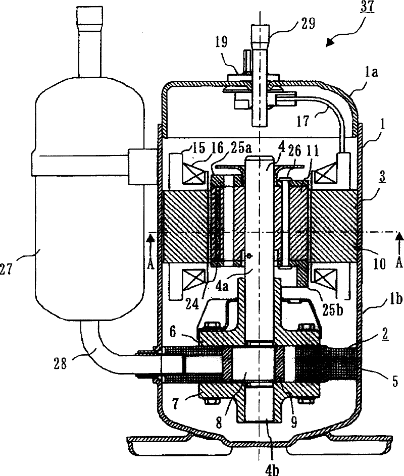
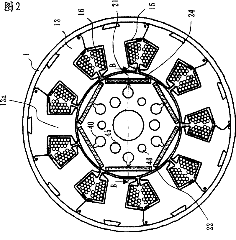
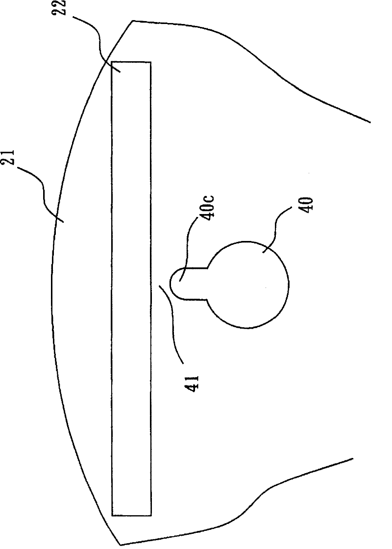
[0036] Figure 1 to Figure 6 is a diagram showing the first embodiment, figure 1 is a sectional view showing the hermetic compressor 37, figure 2 yes means figure 1 A-A sectional view of, image 3 is an enlarged view showing the vicinity of the ventilation hole 40 of the rotor core 21, Figure 4 yes means figure 2 The B-B sectional view, Figure 5 is a block diagram showing a control device 30 for controlling a hermetic compressor 37, Figure 6 is a pulsation diagram showing the compression torque of the hermetic compressor 37 .
[0037] use figure 1 The overall configuration of the hermetic compressor 37 will be described. The hermetic compressor 37 will be described by taking a single-cylinder rotary compressor as an example. The hermetic compressor 37 accommodates a compression element 2 for compressing refrigerant and an electric element 3 for driving the compression element 2 in a hermetic container 1 composed of an upper container 1a and a lower container 1b. ...
no. 2 approach
[0056] In the first embodiment, the hermetic compressor 37 having the rotor 11 in which the permanent magnets 24 are fixed by deforming the thin portion 41 between the magnet insertion hole 22 of the rotor core 21 and the ventilation hole 40 has been described. A method of manufacturing the rotor 11 will be described in the second embodiment.
[0057] Figure 7 It is a figure which shows 2nd Embodiment, and shows an example of the deformation|transformation process of the rotor core 21. exist Figure 7 In (a), the core deformation jig 38 is prepared for the rotor core 21 in which the electromagnetic steel sheets are bonded by lamination and riveting (here, six deformation jigs are integrally formed). exist Figure 7 In (b), the core deforming jig 38 is inserted into the six ventilation holes 40 of the rotor core 21 to deform the thin-walled portion 41 near one axial end to narrow the radial width of the ventilation holes 40 . exist Figure 7 In (c), the core deformation j...
no. 3 approach
[0060] Figure 8 It is a figure which shows 3rd Embodiment, and is a refrigerant circuit diagram of an air conditioner. Such as Figure 8 As shown, the refrigerant circuit of the air conditioner is composed of a hermetic compressor 37, a four-way valve 50, an outdoor heat exchanger 51, a decompression device 52 (electronic expansion valve), an indoor heat exchanger 53, and an accumulator 54 of the refrigerant circuit. .
[0061] Such as Figure 8 As shown by the solid line, during the cooling operation, the refrigerant flows through the hermetic compressor 37, the four-way valve 50, the outdoor heat exchanger 51, the decompression device 52, the indoor heat exchanger 53, the four-way valve 50, and the refrigerant circuit. Sequential flow of accumulator 54 and hermetic compressor 37 .
[0062] Such as Figure 8 As shown by the dotted line, during heating operation, the refrigerant flows through the hermetic compressor 37, the four-way valve 50, the indoor heat exchanger 53...
PUM
 Abstract
Description
Claims
Application Information