
Pedal device for vehicle

a technology for pedals and vehicles, applied in mechanical control devices, process and machine control, instruments, etc., can solve the problems of increasing the number of components, increasing the cost, and increasing the complexity of configuration, so as to reduce the fatigue of the driver, reduce the size of the pedal, and simplify the effect of configuration

Active Publication Date: 2020-09-17
SL CORP
View PDF0 Cites 2 Cited by
  • Summary
  • Abstract
  • Description
  • Claims
  • Application Information

AI Technical Summary

Benefits of technology

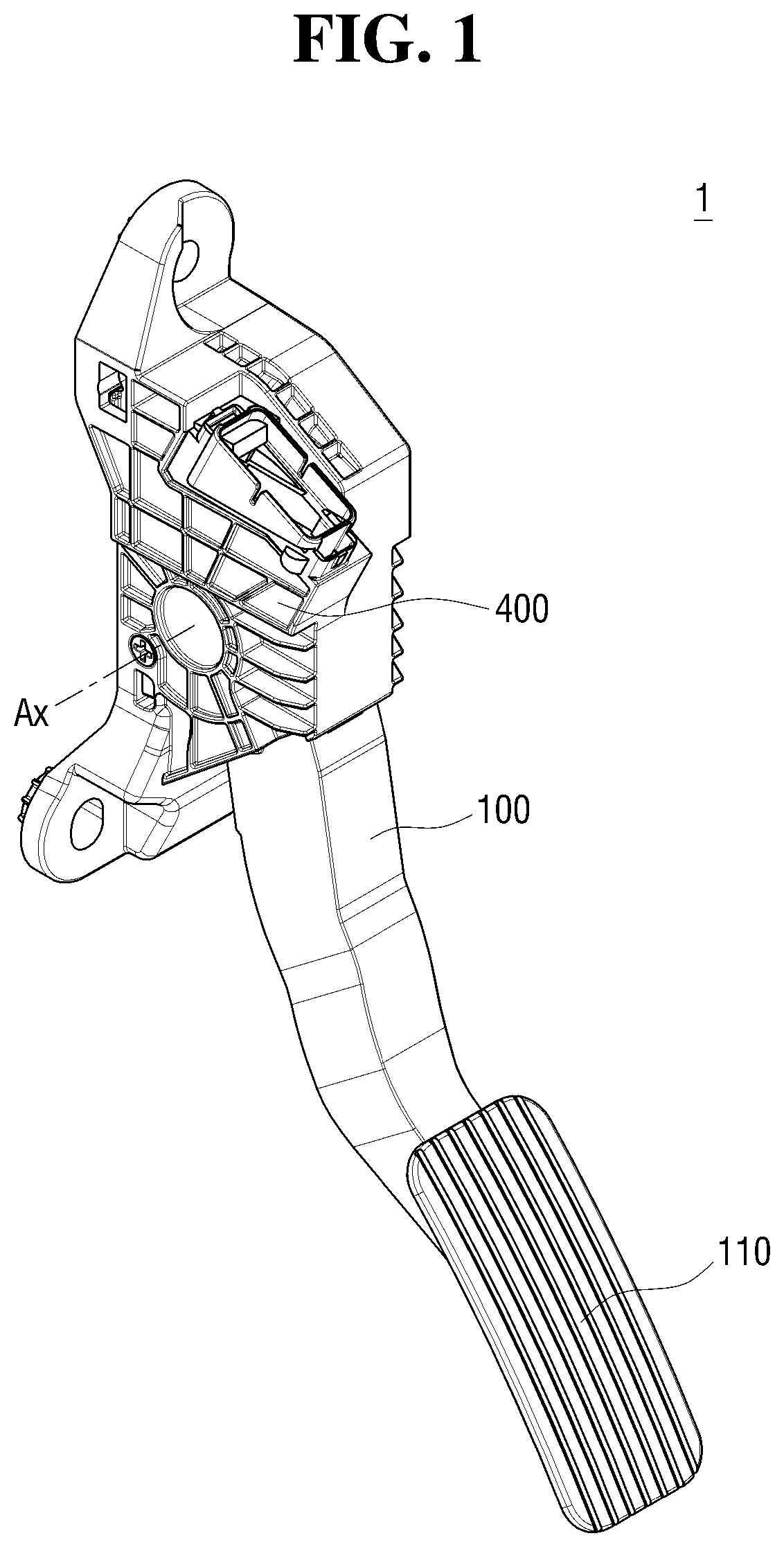
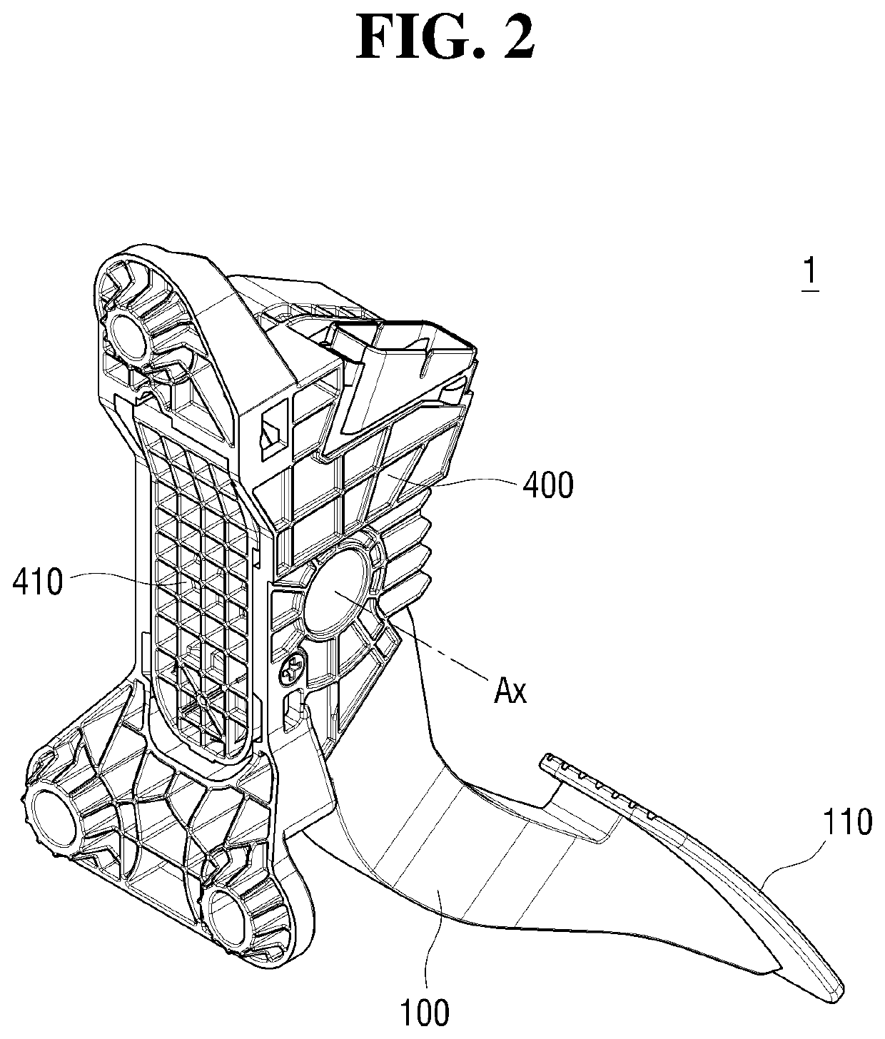
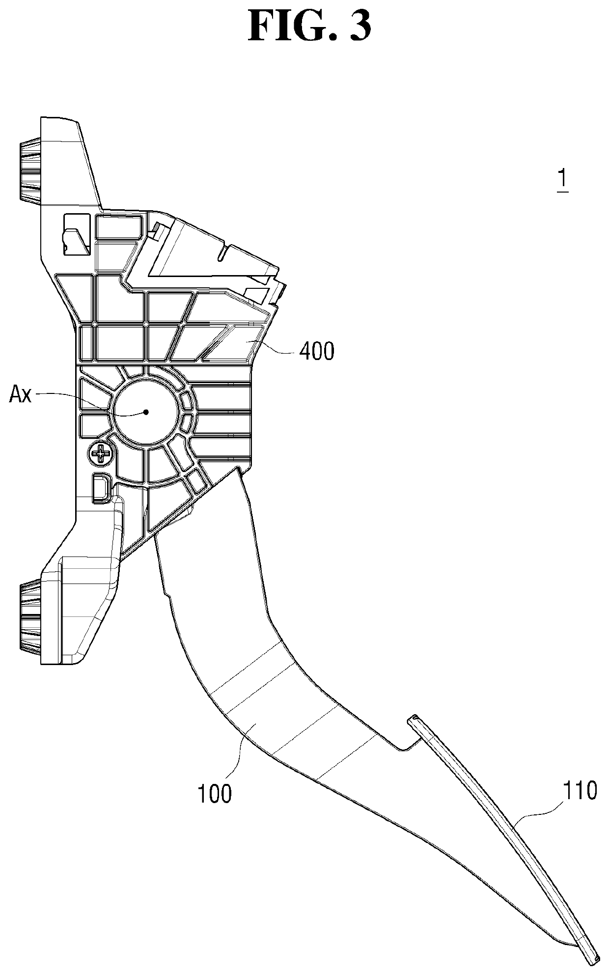
This patent describes a pedal device for a vehicle that generates friction to reduce the fatigue of the driver during operation. The device includes a friction force generator that includes a rotating unit, an extension, a lever, and an elastic member. By pressing the pedal, the lever applies a force to the rotating unit to increase friction between the inner surface of the rotating unit and the outer surface of the shaft of the pedal housing. This hysteresis effect helps to make the pedaling experience more comfortable for the driver. The design is simple and prevents the size of the pedal from increasing. Additionally, the device includes a sensor to accurately detect the position of the pedal.

Problems solved by technology

However, providing a separate device for generating hysteresis when the driver operates the pedal presents a possibility that the number of components increases, and thus, the configuration becomes more complicated and the cost increases.
When the driver operates the pedal, friction forces of different magnitudes are generated depending on a magnitude of an operating force applied to the pedal, and the friction forces act in different directions when the driver steps on the pedal and when the driver releases the foot from the pedal, thereby generating hysteresis, which may reduce the fatigue of the driver for the pedaling operation.

Method used


Image

  • Pedal device for vehicle
  • Pedal device for vehicle
  • Pedal device for vehicle

Examples


Embodiment Construction

[0036]Advantages and features of the present disclosure and methods of accomplishing the same may be understood more readily by reference to the following detailed description of exemplary embodiments and the accompanying drawings. The present disclosure may, however, be embodied in many different forms and should not be construed as being limited to the exemplary embodiments set forth herein. Rather, these exemplary embodiments are provided so that this disclosure will be thorough and complete and will fully convey the concept of the disclosure to those skilled in the art, and the present disclosure will only be defined by the appended claims. Throughout the specification, like reference numerals in the drawings denote like elements. In some exemplary embodiments, well-known steps, structures and techniques will not be described in detail to avoid obscuring the disclosure.

[0037]The terminology used herein is for the purpose of describing particular exemplary embodiments only and is...


PUM


Abstract

A pedal device for a vehicle includes a pedal arm that is rotatable about a rotational axis in a pedal housing, a pedal reaction force generator for generating a pedal reaction force in a direction opposite to a direction in which an operating force of the pedal arm is applied via a pedal pad formed on the pedal arm, a friction force generator comprising a contact disposed at an end of the pedal arm proximate to the rotational axis and a contact surface formed on an inner surface of the pedal housing to be in contact with the contact of the pedal arm, and a position detection unit for detecting a position of the pedal arm. The position detection unit includes a magnet, in which two or more poles are arranged in a displacement direction and in a direction perpendicular to the displacement direction.

Description

CROSS-REFERENCE TO RELATED APPLICATION[0001]This application claims the benefit of priority from Korean Patent Application No. 10-2019-0029832 filed on Mar. 15, 2019 and Korean Patent Application No. 10-2020-0027104 filed on Mar. 4, 2020, which applications are herein incorporated by reference in their entirety.BACKGROUND1. Technical Field[0002]The present disclosure relates to a pedal device for a vehicle, and more particularly to a pedal device for a vehicle capable of generating hysteresis in a pedal reaction force when a driver operates a pedal.2. Description of the Related Art[0003]In general, an accelerator pedal provided in a vehicle is a device for accelerating the vehicle by adjusting the amount of air aspirated into an engine or the amount of fuel injected into the engine depending on an angle to which the pedal rotates by driver's stepping force. There are two types of accelerator pedals: a pendant type that is installed by hanging on a dash panel; and an organ type that ...

Claims


Application Information

Patent Timeline
Patent Type & Authority Applications(United States)
IPC IPC(8): G05G1/38G05G1/44G05G5/05G05G5/03
CPCG05G5/05G05G1/38G05G5/03G05G1/44
Inventor KANG, WOOJINAN, CHANGWENHWANG, INTAE
Owner SL CORP
Learn More