Camera unit and apparatus for monitoring vehicle periphery

a camera unit and periphery technology, applied in the direction of pedestrian/occupant safety arrangement, television system, instruments, etc., can solve the problems of image deterioration and further worsening of achieve the effect of improving visual confirmation of images, wide visual field, and picking up

Inactive Publication Date: 2005-04-21
AUTONETWORKS TECH LTD +2
View PDF20 Cites 53 Cited by
  • Summary
  • Abstract
  • Description
  • Claims
  • Application Information

AI Technical Summary

Benefits of technology

[0011] It is an object of the invention to provide a camera unit and an apparatus for monitoring a vehicle periphery, which are capable of picking up a wide range of visual field while adequately adjusting the visual fields in the horizontal and vertical directions, and at the same time, attempting to improve visual confirmation of images displayed.

Problems solved by technology

In addition, a ghost image, flare, etc., occur due to the unnecessary light, wherein visual confirmation of images is further worsened.
Also, in a normal fisheye lens, a picked-up image is taken to be smaller in the peripheral portions than at the central portion due to distortion, wherein if the peripheral portions of the picked-up image are enlarged, the image deterioration becomes particularly remarkable.

Method used


Image

  • Camera unit and apparatus for monitoring vehicle periphery
  • Camera unit and apparatus for monitoring vehicle periphery
  • Camera unit and apparatus for monitoring vehicle periphery

Examples


embodiment 1

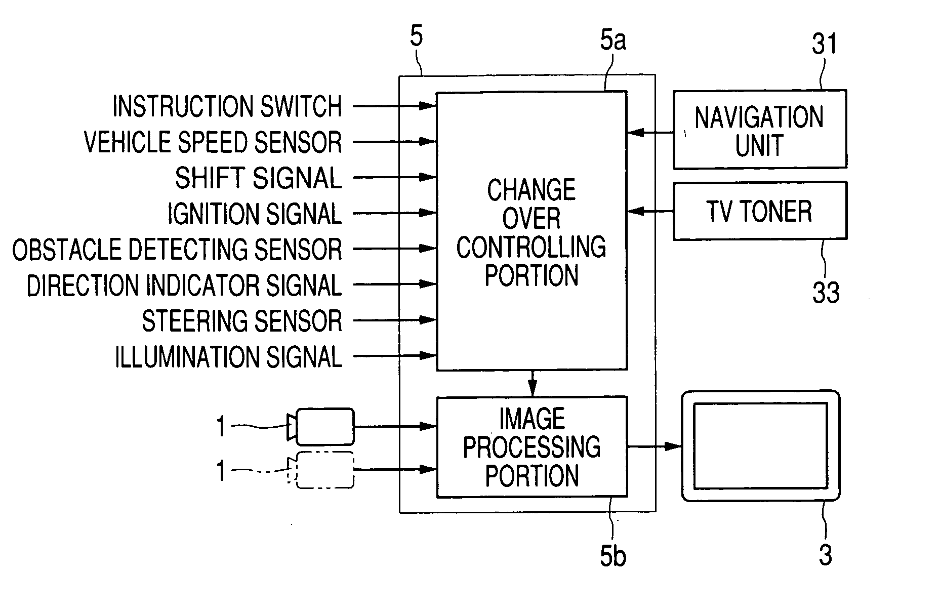
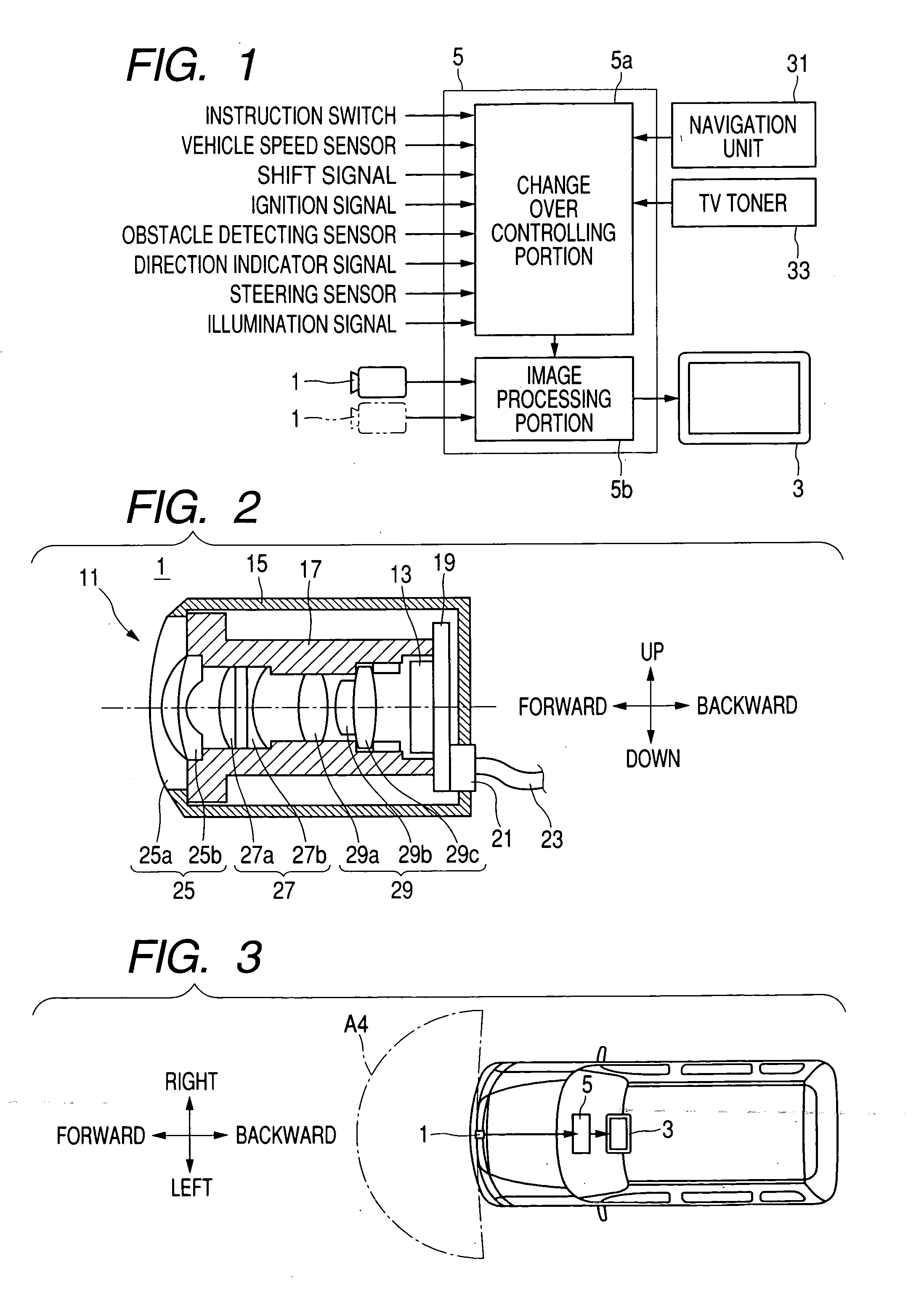
[0075]FIG. 1 is a block diagram of an apparatus for monitoring a vehicle periphery according to Embodiment 1 of the present invention, and FIG. 2 is a longitudinally sectional view showing a construction of a camera unit equipped in the apparatus for monitoring a vehicle periphery in FIG. 1. As shown in FIG. 1, the apparatus for monitoring a vehicle periphery is provided with a camera unit 1, a display unit 3 and a controller unit 5. Also, in the present Embodiment, the construction includes a single camera 1. However, as shown with hypothetical lines in FIG. 1, the construction may include two or more camera units.

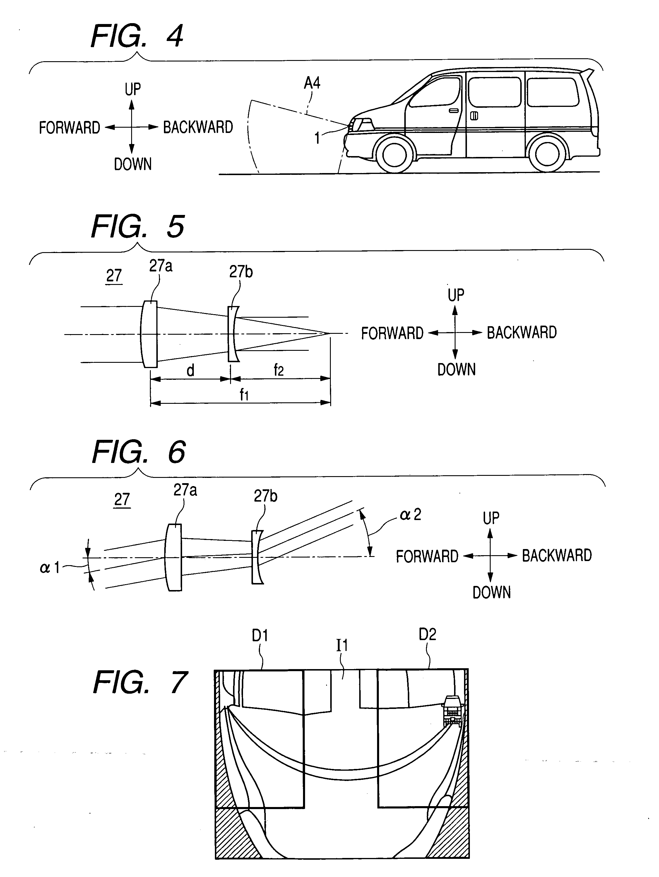
[0076] The camera unit 1 has a construction such as shown in FIG. 2 and is installed at the middle part of the front end portion of a vehicle as shown in FIG. 3 and FIG. 4, wherein the camera unit 1 is devised so that it can pick up a wide range A4 of visual field from the forward front (including a diagonally downward portion forward of a vehicle) of the vehicle to the ...

embodiment 2

[0105]FIG. 11 and FIG. 12 are views showing installation patterns of a camera unit in an apparatus for monitoring a vehicle periphery according to Embodiment 2 of the invention. In the present Embodiment, as shown in FIG. 11 and FIG. 12, a camera unit 1 whose construction is almost identical to that of the camera unit 1 according to Embodiment 1 is installed at the middle part at the rear portion of a vehicle, and is devised so that a wide visual field range A5 from the rear side backward of a vehicle (which includes a diagonally downward portion backward of the vehicle) to the left and right sides. The other construction is almost identical to that of Embodiment 1, and a description thereof is omitted herein.

[0106] As an example for controlling changeover of the display content of the display unit 3, for example, when it is detected by the controlling unit 5 based on a shift-position signal that the shift position is moved to R (Reverse), the display content of the display unit 3 ...

embodiment 3

[0108]FIG. 13 and FIG. 14 are views showing installation patterns of a camera unit in an apparatus for monitoring a vehicle periphery according to Embodiment 3 of the invention. In the present Embodiment, as shown in FIG. 13 and FIG. 14, a camera unit the construction of which is almost identical to that of the camera unit 1 according to Embodiment 1 is installed at a corner part of a vehicle (in the present Embodiment, at the left side corner portion at the front side of a vehicle (for example, at the corner of a bumper)) and is devised so that it can pick up a wide range A6 of visual field at the periphery of the corner portion. Other construction is almost identical to that of Embodiment 1, and description thereof is omitted herein.

[0109] As an example of controlling changeover of the display content of the display unit 3, for example, where it is detected by an obstacle detecting signal from an obstacle detecting sensor (not illustrated) installed at the left side corner portio...


PUM


Abstract

In a camera unit, a lens system may be configured by a first lens group (wide-angle lens system) whose a field angle in a horizontal direction is 120 degrees or more, a second lens group (anamorphic lens system) whose anamorphic ratio is 1.5 or more, and a third lens group (image-forming lens system). A lens system may be configured so that the amount of change in image height with respect to a change of an image angle is made larger at the peripheral parts than at the center portion of a formed image.

Description

BACKGROUND OF THE INVENTION [0001] 1. Field of the Invention [0002] The present invention relates to a camera unit and an apparatus for monitoring a vehicle periphery. [0003] 2. Description of the Related Art [0004] For uses in a vehicle and monitoring, it is highly recommended that a wider range of visual field can be picked up by a single camera. In this case, there are many cases where it is desired that the visual field range is wider in the vertical direction than in the horizontal direction. [0005] A camera unit having a prism at the front side of its camera and devised to pick up images in three directions are available (JP-A-2000-89301). By installing the camera unit at the front end part of a vehicle, visual field ranges A1 and A2 in the left and right directions forward of the vehicle and a diagonally downward visual field range A3 forward thereof can be simultaneously picked up as shown in FIG. 33 and FIG. 34. [0006] An apparatus for visually confirming the rearward of th...

Claims


Application Information

Patent Timeline
Patent Type & Authority Applications(United States)
IPC IPC(8): G03B15/00B60R1/00B60R11/02B60R21/00G02B13/06G03B37/00G08G1/16H04N5/225H04N7/18
CPCB60R1/00B60R2300/105B60R2300/30H04N7/183B60R2300/806G02B13/06B60R2300/40
Inventor IMOTO, MASAYOSHIMATSUI, AKINORI
Owner AUTONETWORKS TECH LTD
Why Eureka
Try Eureka