Vertebral prosthesis

a technology for vertebrae and prostheses, applied in the field of vertebrae prostheses, can solve problems such as disc degeneration, back pain, back pain,

Inactive Publication Date: 2005-04-21
SPINAL GENERATIONS
View PDF57 Cites 154 Cited by
  • Summary
  • Abstract
  • Description
  • Claims
  • Application Information

AI Technical Summary

Problems solved by technology

The motion and support functions of the spine, in combination with the many interlocking parts and nerve roots associated with the spinal column can result in back pain due to various reasons.
Such ba

Method used


Image

  • Vertebral prosthesis
  • Vertebral prosthesis
  • Vertebral prosthesis

Examples


Embodiment Construction

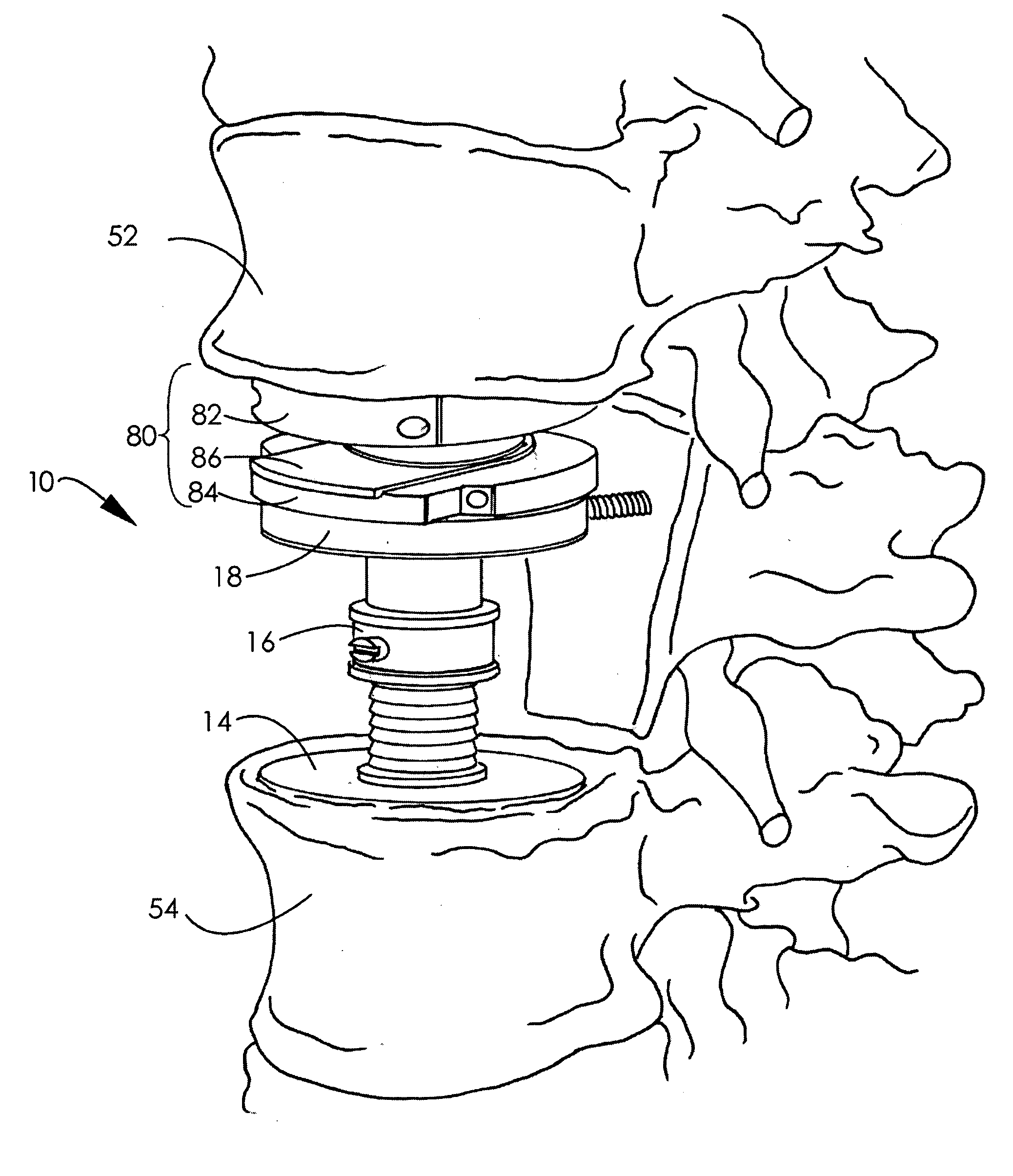
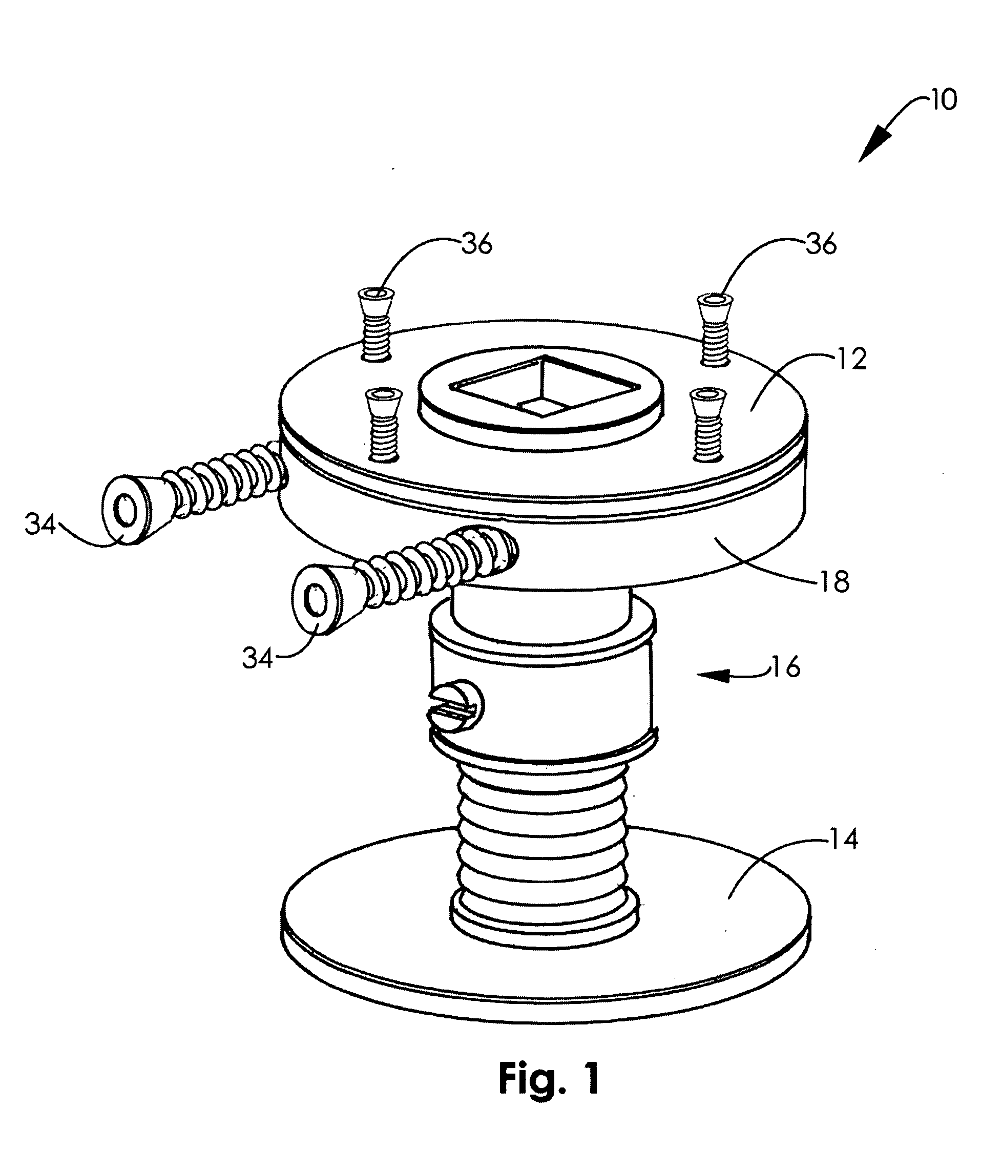
[0035] Referring to FIG. 1, according to an exemplary embodiment, a vertebral prosthesis or artificial vertebral body, shown as vertebral prosthesis 10, includes a pair of endplates, shown as endplate trays 12, 14. The endplate trays 12, 14 are connected to one another by a support, shown as shaft 16. A pedicle screw retainer or support 18 may be coupled to the shaft 16 and connected to one of the endplate trays 12, 14. In the depicted embodiment, pedicle screw support 18 is affixed to shaft 16 adjacent the upper endplate tray 12.

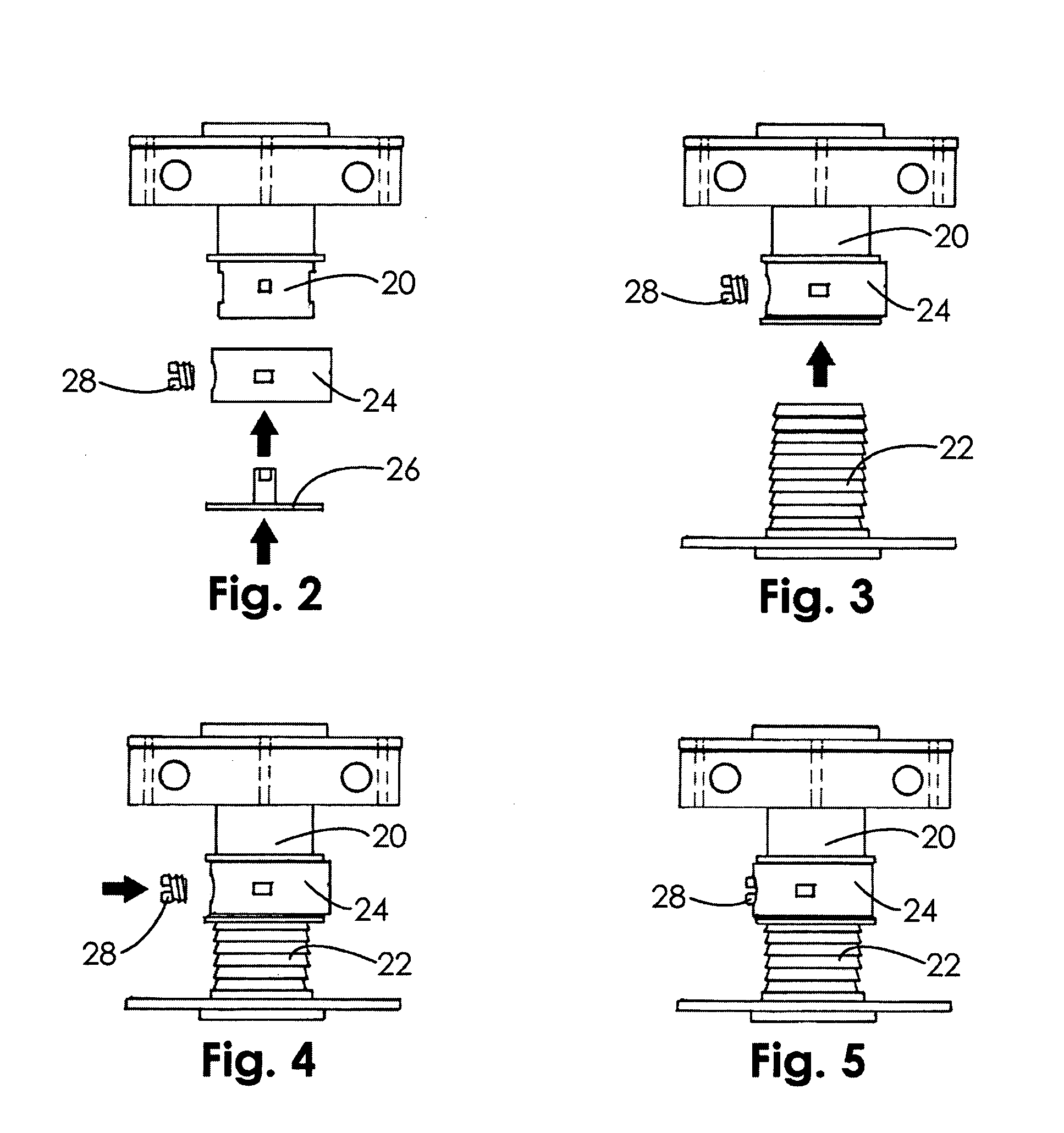
[0036] Referring to FIGS. 2-5, in an exemplary embodiment, the vertebral prosthesis 10 has a shaft upper portion 20 and a shaft lower portion 22. A locking ring 24 may be held in place by a washer 26 and used to connect lower portion 22 to upper portion 20. In the embodiment shown in FIGS. 2-5, shaft lower portion 22 is received within cylindrically shaped shaft upper portion 20 and fixed in place by a fixation device, shown as screw 28. The use of locking...


PUM


Abstract

A vertebral prosthesis is adapted to be implanted adjacent a spinal disc prosthesis. According to one embodiment, the vertebral prosthesis includes a shaft and an endplate coupled to one end of the shaft. The endplate is adapted to be implanted adjacent a disc prosthesis, thereby obviating the need to fuse the endplate to an adjacent vertebral body.

Description

FIELD OF THE INVENTION [0001] The present invention relates to a vertebral prosthesis, used to replace a spinal vertebra. In particular, the present invention relates to a vertebral prosthesis that is used in conjunction with disc prostheses to avoid the need for a spinal fusion procedure. BACKGROUND OF THE INVENTION [0002] The spinal column is comprised of twenty-six interlocking vertebrae. These vertebrae are separated by discs. The spine provides load bearing support for one-half of the body's mass and it protects the nerves of the spinal column. The discs provide shock absorption and facilitate the bending of the spine. [0003] The combination of the vertebrae and discs at each vertebral segment allows for motion of the spine, in particular, flexing, rotation, and extension. The motion and support functions of the spine, in combination with the many interlocking parts and nerve roots associated with the spinal column can result in back pain due to various reasons. Such back pain ...

Claims


Application Information

Patent Timeline
IPC IPC(8): A61FA61F2/00A61F2/30A61F2/44
CPCA61F2/44A61F2220/0033A61F2/4425A61F2002/30331A61F2002/30469A61F2002/30507A61F2002/3055A61F2002/30563A61F2002/30601A61F2002/30649A61F2002/30774A61F2002/30841A61F2002/30878A61F2220/0025A61F2/442
Inventor SWEENEY, PATRICK J.
Owner SPINAL GENERATIONS
Why Eureka
Try Eureka