
Double-layer roller blind

a double-layer roller blind and roller blind technology, applied in the field of roller blinds, can solve the problems that the conventional design of double-layer roller blinds b>80/b> is still not satisfactory in function, and achieve the effect of high stability and nice looking

Inactive Publication Date: 2005-04-28
NIEN MADE ENTERPRISE CO LTD
View PDF8 Cites 55 Cited by
  • Summary
  • Abstract
  • Description
  • Claims
  • Application Information

AI Technical Summary

Benefits of technology

[0007] It is the primary objective of the present invention to provide a double-layer roller blind having two shades, which keeps the front and rear shades smoothly close to each other, giving a nice looking and high stability of light shading.

Problems solved by technology

The aforesaid conventional design of double-layer roller blind 80 is still not satisfactory in function.

Method used


Image

  • Double-layer roller blind
  • Double-layer roller blind
  • Double-layer roller blind

Examples


Embodiment Construction

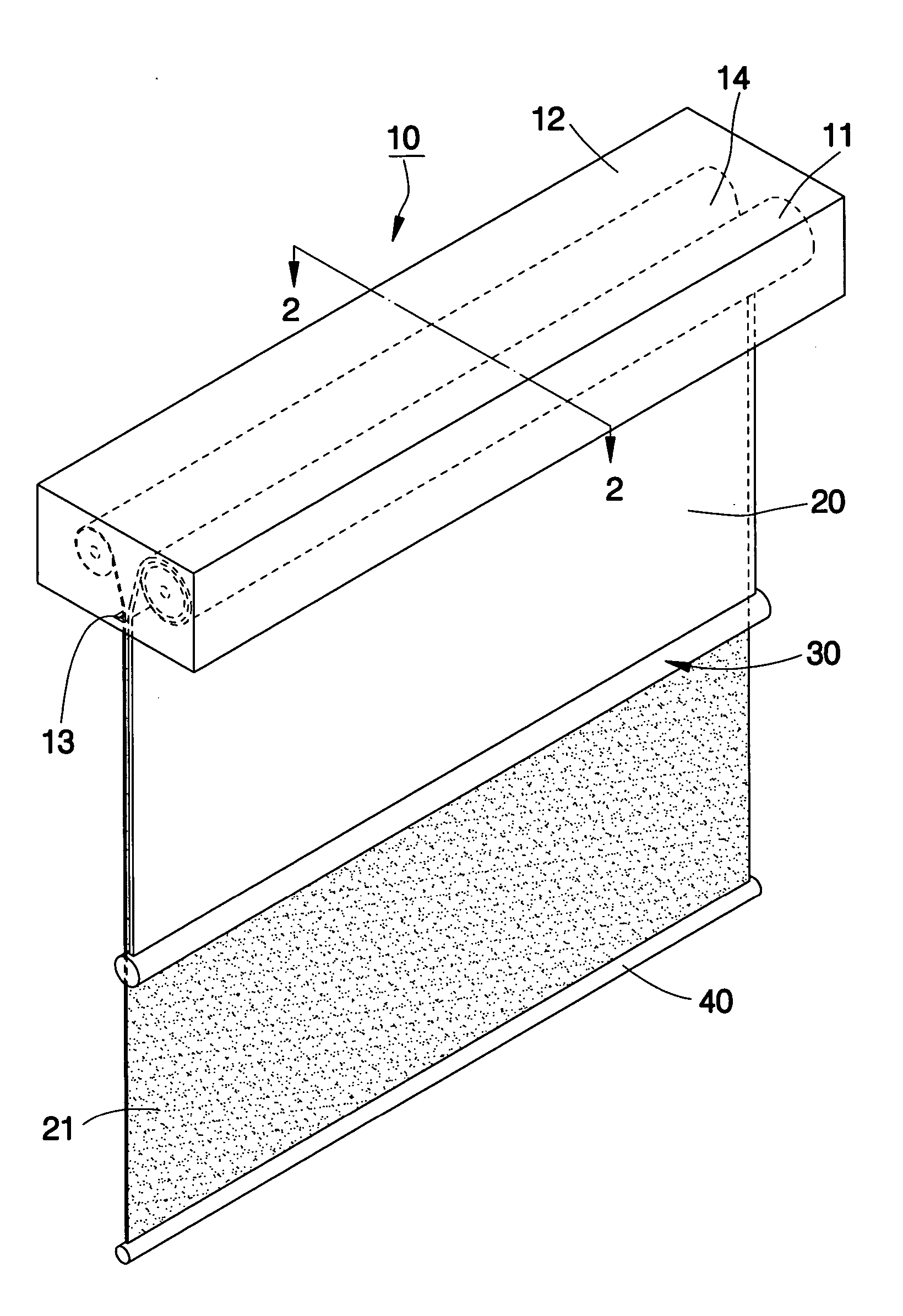
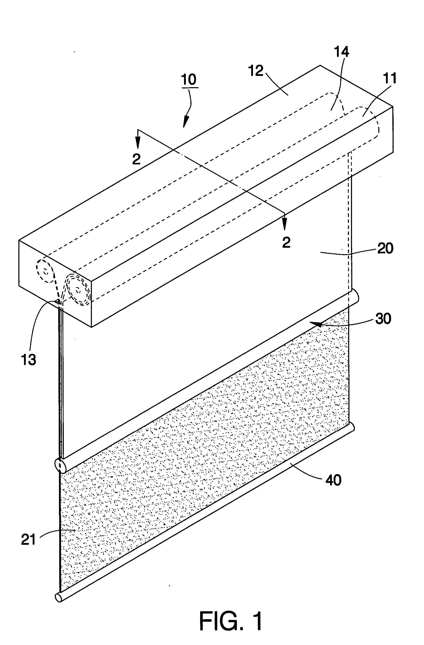
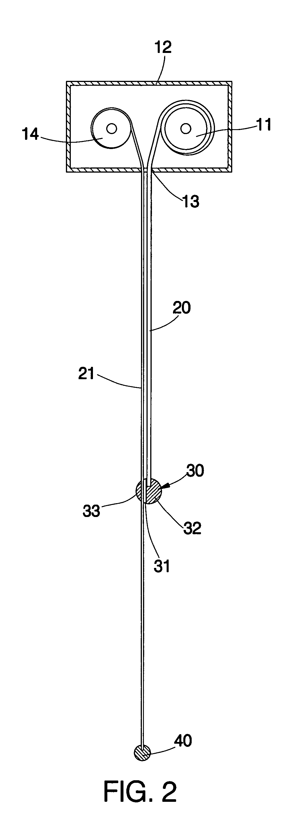
[0018] Referring to FIGS. 1 and 2, a double-layer roller blind 10 in accordance with the first preferred embodiment of the present invention is shown comprised of a first roller 11, a second roller 14, a first shade 20, a second shade 21, a first bottom bar 30, and a second bottom bar 40.

[0019] The first roller 11 is a cylindrical member transversely pivotally fastened to the top side of the window (not shown). According to this embodiment, the first roller 11 is fastened pivotally with the inside of an elongated box 12, which is fixedly provided at the top side of the window. The first roller 11 can be controlled to rotate on its own axis inside the elongated box 12. It is to be understood that the method of controlling the first roller to rotate can be achieved by means of any of a variety of conventional techniques, for example, by means of the control of a lift cord, a spring winding mechanism, or a wired or wireless controller. The elongated box 12 has a narrow elongated slot ...


PUM


Abstract

A double-layer roller blind includes a first roller and a second roller horizontally arranged in parallel at the top side of a window, a first shade fastened with a top edge thereof to the first roller, a first bottom bar fastened to a bottom edge of the first shade, a second shade fastened with a top edge thereof to the second roller, and a second bottom bar fastened to a bottom edge of the second shade and suspended below the first bottom bar. The first bottom bar is provided with an insertion space through which the second shade is inserted such that the second shade is kept close to the first shade.

Description

BACKGROUND OF THE INVENTION [0001] 1. Field of the Invention [0002] The present invention relates to a roller blind and more particularly, to a double-layer roller blind having two shades that are smoothly close to each other. [0003] 2. Description of the Related Art [0004] As shown in FIG. 6, a conventional double-layer roller blind 80 is shown comprised of two rollers 81, 82, two shades 83, 84, and two bottom bars 85, 86. The rollers 81, 82 are transversely pivotally fastened to the top side of the window (not shown), and can be respectively rotated by way of a respective lift cord or a motor governed by a remote controller. The shades 83, 84 have the respective top edge respectively fastened to the rollers 81, 82 such that the rollers 81, 82 can be rotated to roll up or let off the shades 83, 84. The shades 83, 84 are usually made of different fabrics, i.e., the shade 83 which approaches the window has a high transmission rate of light (for example, made of a gauze cloth), the sh...

Claims


Application Information

Patent Timeline
IPC IPC(8): E06B9/24E06B9/42
CPCE06B2009/2452E06B9/42E06B2009/405
Inventor NIEN, MINGPON, DAVID KUEI-TIN
Owner NIEN MADE ENTERPRISE CO LTD
Features
  • Generate Ideas
  • Intellectual Property
  • Life Sciences
  • Materials
  • Tech Scout
  • Unparalleled Data Quality
  • Higher Quality Content
  • 60% Fewer Hallucinations
Learn More