
Wireless Card and Adjustable Antenna of the Same

a technology of adjustable antennas and wireless cards, applied in the direction of antennas, antenna details, protective materials, etc., can solve the problems of not meeting the requirements of good signal reception and transmission, the exposed surface of adjustable antennas cannot have any parting lines or boundary lines between components to meet the surface quality requirements, etc., to enhance the stabilization of manufacturing processes, improve the appearance, and increase the manufacturing yield

Inactive Publication Date: 2008-07-31
BANDRICH
View PDF0 Cites 1 Cited by
  • Summary
  • Abstract
  • Description
  • Claims
  • Application Information

AI Technical Summary

Benefits of technology

[0012]Another object of the present invention is to provide an adjustable antenna for a wireless card so that the entire appearance of the wireless card is good look, which enhances signal reception and transmission quality and to increase manufacturing yield of the wireless card.
[0018]In addition, since the antenna and the inner base are encapsulated by the outer casing with embedded molding, the appearance of the adjustable antenna does not have any component boundary lines, i.e. the lines between the adjacent components. Thus, the complete appearance of the adjustable antenna is smooth, clean and nice to look at.
[0019]Furthermore, using the multi-stage embedded molding to manufacture the adjustable antenna not only increases manufacturing yield, but also enhances stabile of manufacturing processes.

Problems solved by technology

Antenna dimension, size and location are major design challenges that influence the performance of signal reception and transmission.
Thus, using a single antenna does not satisfy the requirements of good signal reception and transmission.
In other words, the exposed surface of the adjustable antenna cannot have any parting lines or boundary lines between components to meet surface quality requirements.

Method used


Image

  • Wireless Card and Adjustable Antenna of the Same
  • Wireless Card and Adjustable Antenna of the Same
  • Wireless Card and Adjustable Antenna of the Same

Examples


Embodiment Construction

[0028]Reference will now be made in detail to the present preferred embodiments of the invention, examples of which are illustrated in the accompanying drawings. Wherever possible, the same reference numbers are used in the drawings and the description to refer to the same or like parts.

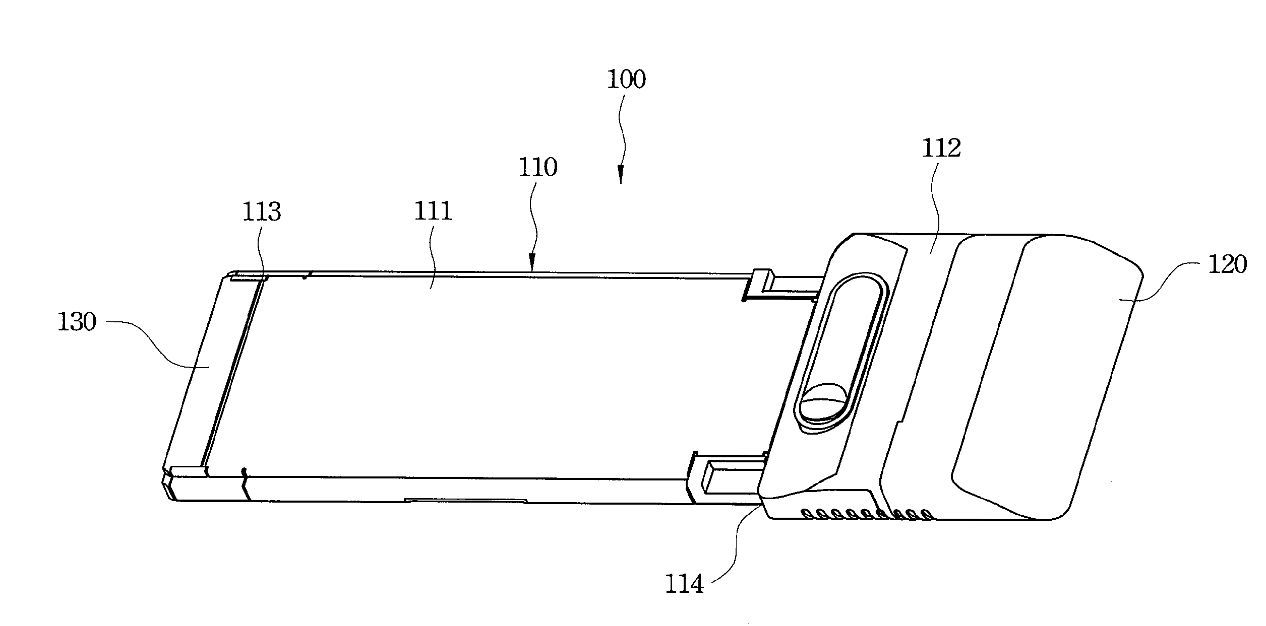
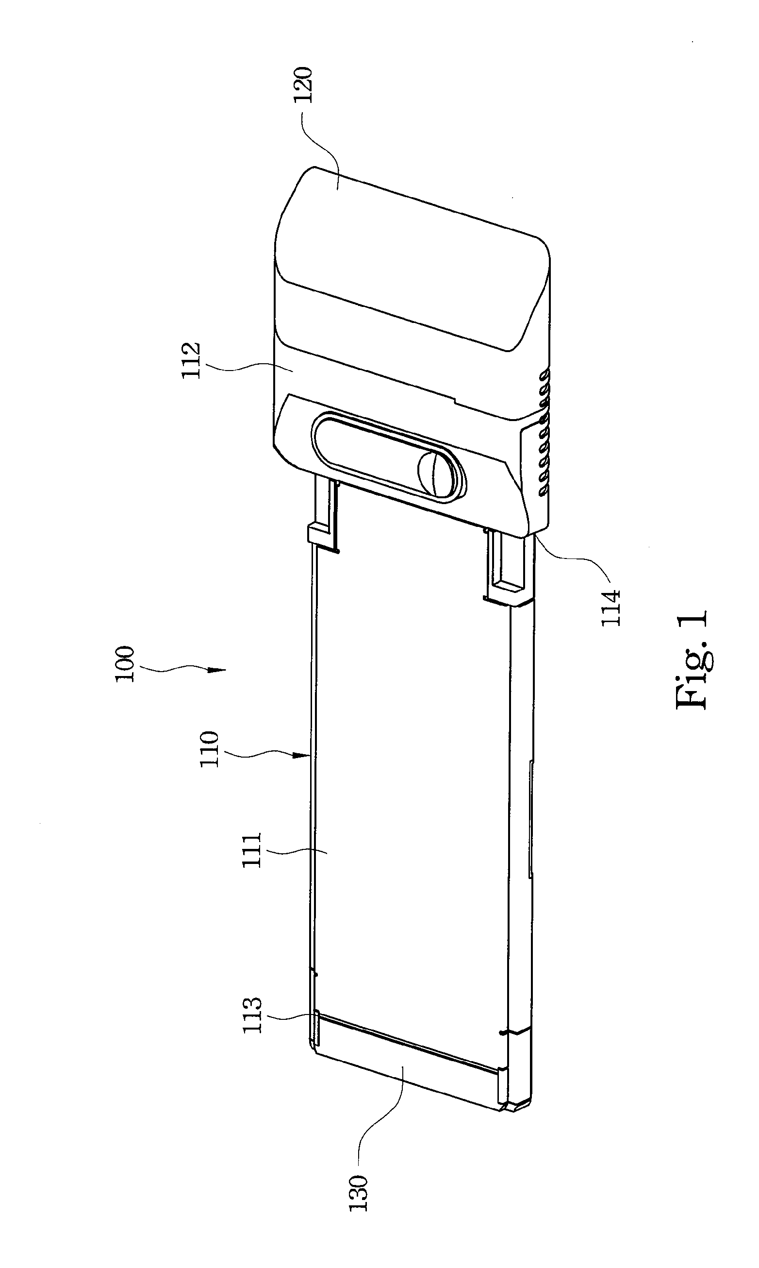
[0029]Refer to FIG. 1 and FIG. 2. An embodiment of a wireless card 100 in accordance with the present invention comprises a body 110, an adjustable antenna 120, a transmission interface 130 and a circuit device. The body 110 comprises an insertion portion 111 and an outer portion 112. The circuit device is mounted inside the body 110.

[0030]The insertion portion 111 has a first end 113 and a second end 114 opposite to the first end 113. The transmission interface 130 is connected to the first end 113 and is electrically connected to the circuit device. When the wireless card 100 is used to establish wireless communication, the insertion portion 111 is inserted into a slot of a portable electronic devi...


PUM


Abstract

A wireless card includes a body, a circuit device and an adjustable antenna assembly. The body includes an insertion portion and an outer portion. The outer portion is connected to an end of the insertion portion. The circuit device is mounted inside the body. The adjustable antenna is adjustably mounted in the outer portion and includes an antenna module. The antenna module includes an inner base, an antenna, at least two molding supporting members and an outer casing. The antenna is attached to the inner base and connected electrically to the circuit device. The molding supporting members are formed on the inner base. The outer casing encapsulates the inner base with the antenna with embedded molding.

Description

BACKGROUND[0001]1. Field of Invention[0002]The present invention relates to a wireless mobile communications device. More particularly, the present invention relates to a wireless card for mobile communications.[0003]2. Description of Related Art[0004]Next generation mobile communications technologies and terminal equipment are continuously developed to satisfy the increasing demands of mobility. This mobile communication technology and terminal equipment seeks not only to improve communication speed and quality, but also to provide communication terminals that are convenient to use, look good and are portable to meet consumer demands.[0005]Typically, portable information technology (IT) products, such as laptops require wireless cards to enable wireless communications. Wireless cards have various designs and features based on the specifications of different wireless communication protocols. Developments and growth of the next generation mobile communications technologies increase c...

Claims


Application Information

Patent Timeline
Patent Type & Authority Applications(United States)
IPC IPC(8): H01Q1/42H01Q1/40
CPCH01Q1/08H01Q9/42H01Q1/2275
Inventor HSU, GARY
Owner BANDRICH
Features
  • Generate Ideas
  • Intellectual Property
  • Life Sciences
  • Materials
  • Tech Scout
  • Unparalleled Data Quality
  • Higher Quality Content
  • 60% Fewer Hallucinations
Learn More