Wireless Card and External Antenna Connecting Device of the Same

a wireless card and connecting device technology, applied in the field of wireless mobile communications devices, can solve the problems of only obtaining better reception and transmission quality, users cannot change or expand the dimensions and locations of built-in or adjustable antennas, and single antennas cannot meet the dual requirements of good signal reception and transmission, etc., to achieve the effect of enhancing the application and expansion of the wireless card, convenient and easy to use, and quick and convenient acquisition

Inactive Publication Date: 2008-07-03
BANDRICH
View PDF6 Cites 2 Cited by
  • Summary
  • Abstract
  • Description
  • Claims
  • Application Information

AI Technical Summary

Benefits of technology

[0017]Consequently, the wireless card provides a capability of connecting an external antenna. When there is no need to use an external antenna, covering the chamber by the cover hides the external antenna connector. The cover can be designed with the entire wireless card to make the entire appearance of the wireless card aesthetic, clean and nice to look at. Thus, applications and expansion of the wireless card have been enhanced, and the external antenna connecting device is convenient and easy to use.
[0018]In addition, light beams produced by the illuminating device enter ...

Problems solved by technology

Antenna size and location are major design challenges that influence the performance of signal reception and transmission.
Thus, using a single antenna cannot satisfy the dual requirements of good signal reception and transmission.
However, end users cannot change or expand the dimensions and locations of the built-in or adjustable antennas.
Users can only obtain better reception and transmission quality by adjusting orientations of the adjustable antenna.
However, the convention wireless ca...

Method used


Image

  • Wireless Card and External Antenna Connecting Device of the Same
  • Wireless Card and External Antenna Connecting Device of the Same
  • Wireless Card and External Antenna Connecting Device of the Same

Examples


Embodiment Construction

[0026]Reference will now be made in detail to the present preferred embodiments of the invention, examples of which are illustrated in the accompanying drawings. Wherever possible, the same reference numbers are used in the drawings and the description to refer to the same or like parts.

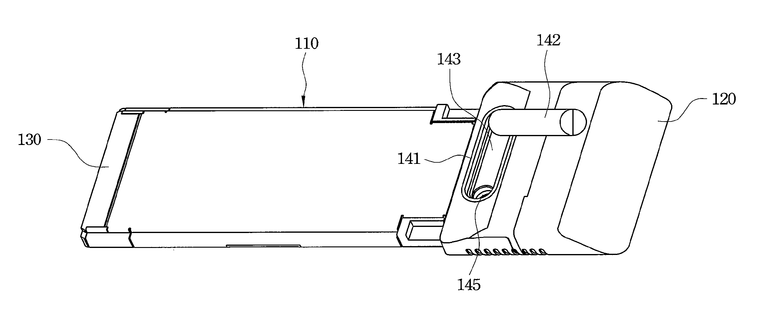
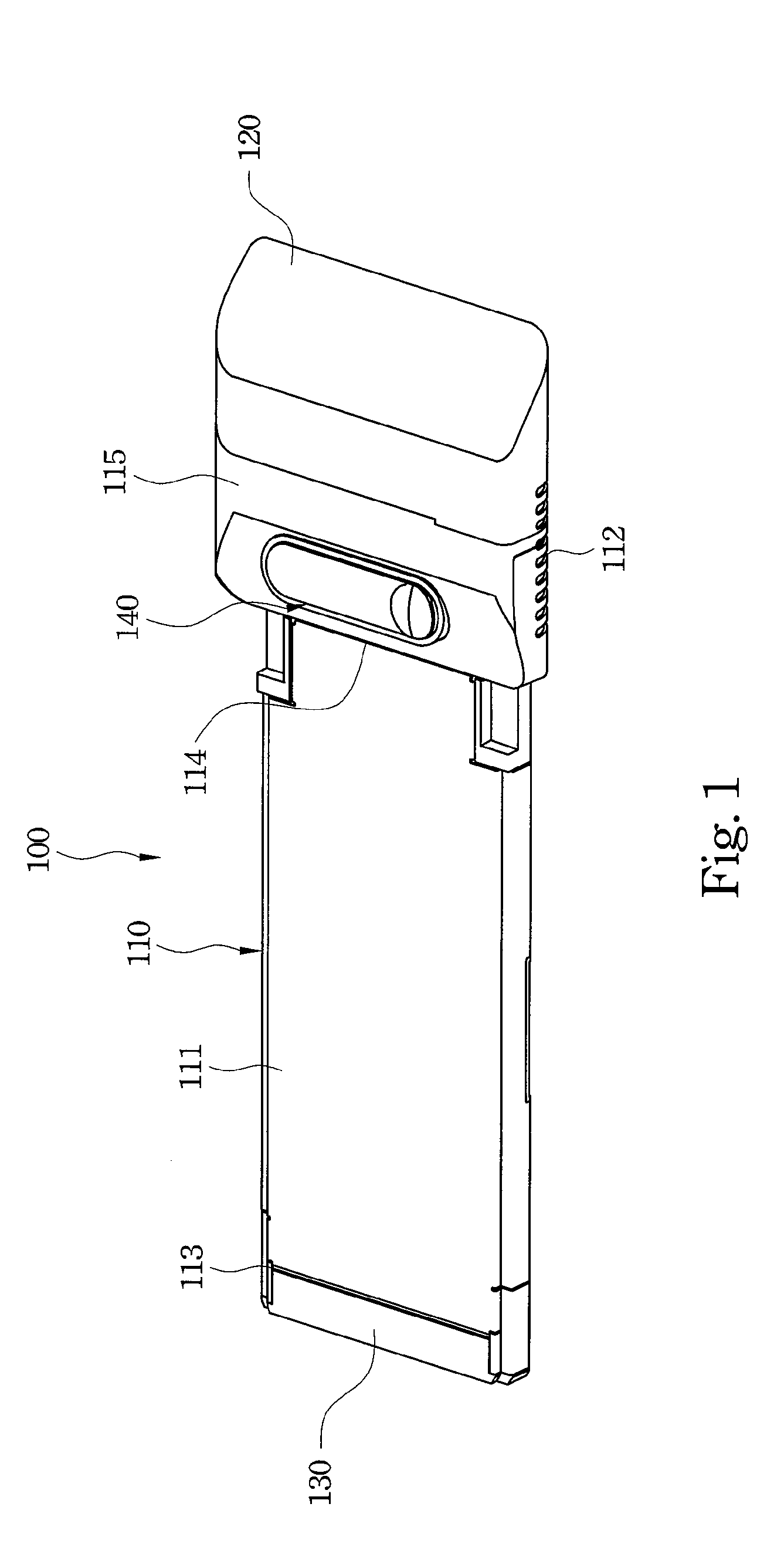
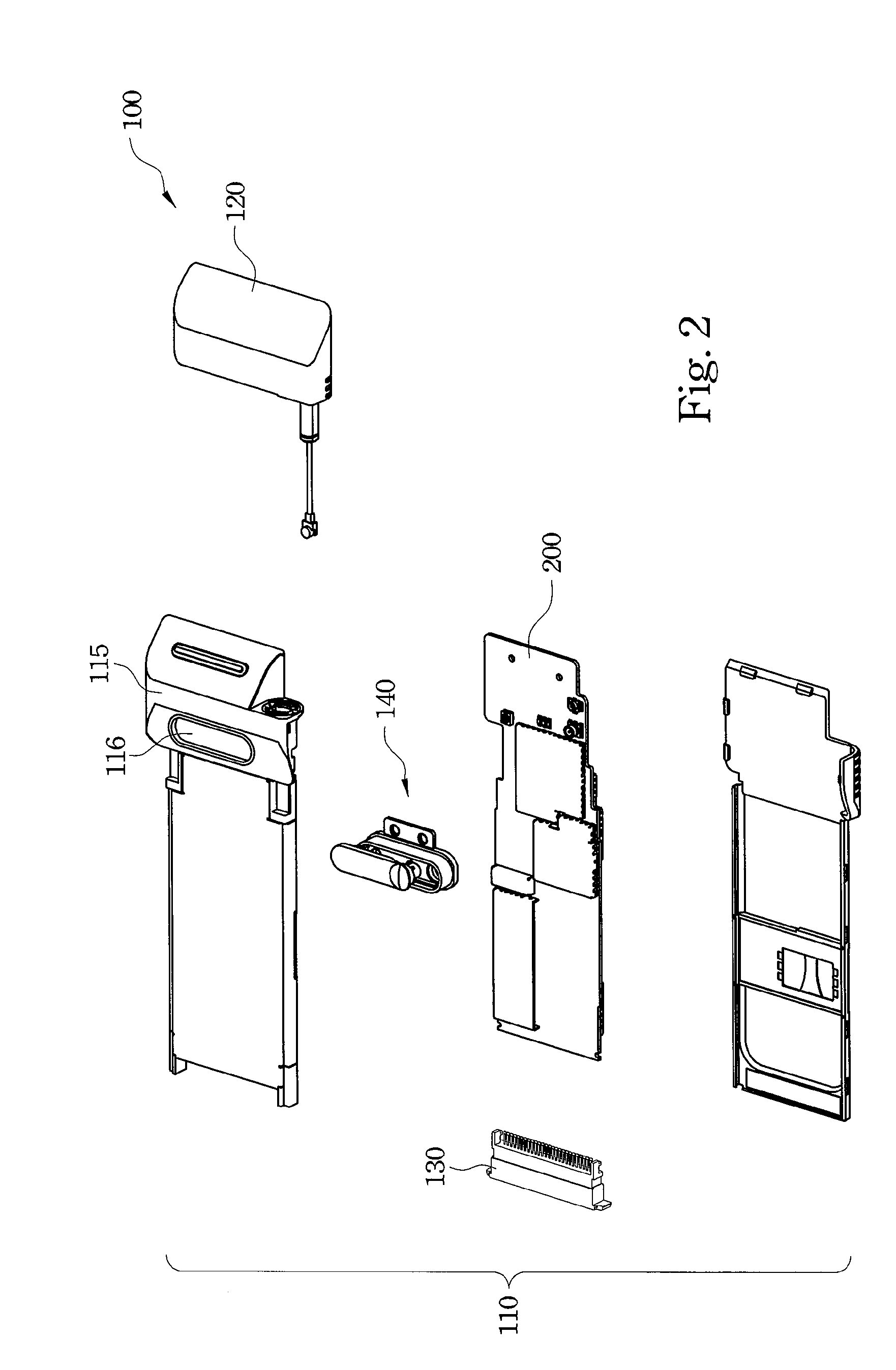
[0027]Refer to FIG. 1 and FIG. 2. A wireless card 100 in accordance with the present invention comprises a body 110, an adjustable antenna 120, a transmission interface 130, an external antenna connecting device 140 and a circuit device 200. The body 110 comprises an insertion portion 111 and an outer portion 112. The circuit device 200 is mounted inside the body 110.

[0028]The insertion portion 111 has a first end 113 and a second end 114 opposite to the first end 113. The transmission interface 130 is connected to the first end 113 and is electrically connected to the circuit device 200. When the wireless card 100 is used to establish a wireless communications environment, inserting the insertion po...


PUM


Abstract

A wireless card includes a body, a circuit device, an adjustable antenna and an external antenna connecting device. The body includes an insertion portion and an outer portion connected to an end of the insertion portion. The circuit device is mounted inside the body. The external antenna connecting device is mounted on the outer portion and includes a connecting base, an external antenna connector and a cover. The connecting base has a chamber in which the external antenna connector is mounted. The cover is mounted on the connecting base to cover the chamber when the external antenna connector is not used to connect an external antenna. The connecting base is made of light-transmitting material, and the circuit device comprises at least one illuminating devices corresponding to the connecting base through which light emitted by illuminating devices enters the connecting base to enhance indications of connection status.

Description

BACKGROUND[0001]1. Field of the Invention[0002]The present invention relates to a wireless mobile communications device. More particularly, the present invention relates to a wireless card for mobile communications.[0003]2. Description of Related Art[0004]Next generation mobile communications technologies and terminal equipment are continuously developed to satisfy the increasing demands of mobility. Those mobile communication technologies and terminal equipment seek not only to improve communication speed and quality, but also provide communication terminals that are convenient to use, look good and are portable to meet consumer demand.[0005]Typically, portable information technology (IT) products, such as laptops require wireless cards to establish a wireless communication environment. The wireless cards have various designs and features based on the specifications of different wireless communication protocols. Especially, developments and the growth of mobile communications techn...

Claims


Application Information

Patent Timeline
IPC IPC(8): H04B7/00
CPCG06K19/07749
Inventor HSU, GARY
Owner BANDRICH
Why Eureka
Try Eureka