
Optical apparatus with dual illuminating devices

a technology of optical apparatus and illumination device, which is applied in the field of optical apparatus, can solve the problems of unfavorable effects of preventing the optical lens of the microscope, inability to meet the brightness requirements of observation, and weak illumination, and achieves the effects of simplifying the optical design of the apparatus, enhancing optical characteristics, and looking ni

Inactive Publication Date: 2008-11-25
ASIA OPTICAL INT LTD
View PDF3 Cites 0 Cited by
  • Summary
  • Abstract
  • Description
  • Claims
  • Application Information

AI Technical Summary

Benefits of technology

[0010]An object of the present invention is to provide an optical apparatus with dual illuminating devices that enable either the upper side or underside of the optical apparatus to be illuminated and have smooth switching manipulations to provide sufficient light beams for the optical apparatus.
[0014]The optical apparatus in accordance with the present invention alters the lighting devices to illuminate objects by rotating the pivoting arm. The optical apparatus adopts inside lighting device to directly illuminate the object stage from the inside of the object stage. The optical apparatus not only provides direct upper side and inside illumination to the object stage to enhance optical characteristics, but also avoids the need of the light hole, which renders the appearance of the entire optical apparatus beautiful and nice to look. The light beams emitted inside the optical apparatus illuminate the underside of the object stage, which simplifies optical designs of the apparatus.
[0015]Further, since the underside illumination of the object stage is provided by the light beams emitted inside the optical apparatus and is not provided by the external light beams, the present invention therefore has both dual illumination and meets the optical brightness requirements for clear object observation when the illumination is altered to the underside illumination. The structure of the apparatus is not complex, operation of the apparatus is smooth and observation effects are clear.

Problems solved by technology

It therefore provides weak illumination and cannot meet the brightness requirements for observation.
The light hole 512 not only influences the appearance of the entire microscope 500, but also results in unfavorable effects for preventing the optical lenses of the microscope 500 from dust.

Method used


Image

  • Optical apparatus with dual illuminating devices
  • Optical apparatus with dual illuminating devices
  • Optical apparatus with dual illuminating devices

Examples


Embodiment Construction

[0025]Reference will now be made in detail to the present preferred embodiments of the invention, examples of which are illustrated in the accompanying drawings. Wherever possible, the same reference numbers are used in the drawings and the description to refer to the same or like parts.

[0026]An embodiment of an optical apparatus with dual illuminating devices in accordance with the present invention can have applications on illumination of electronic appliances, light and sound mechanisms of toys, gifts or cards, or even illuminating mechanisms for buildings. For convenient illustration, the embodiment illustrates an application on optical microscope as follows.

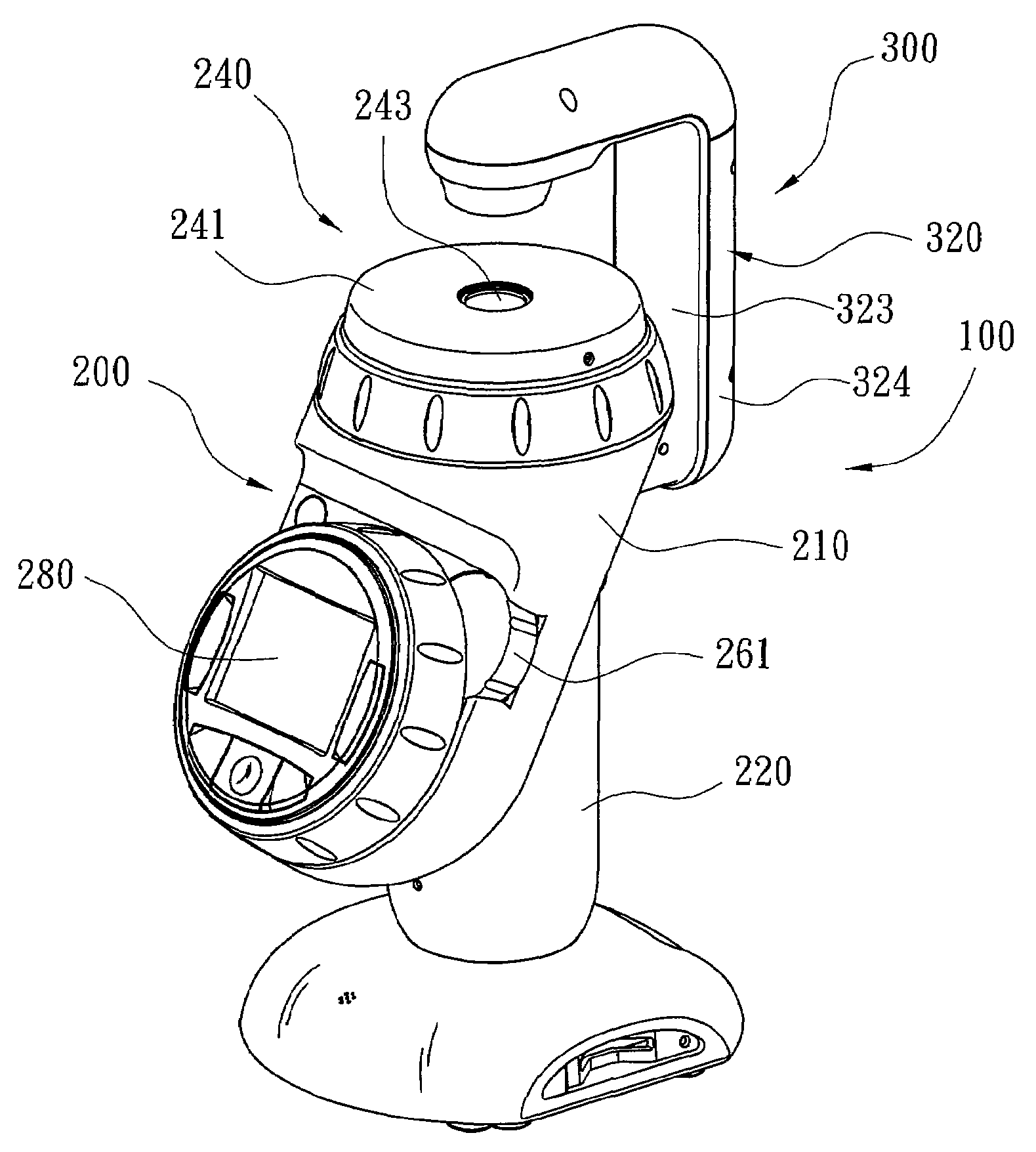
[0027]Refer to FIG. 3, FIG. 4 and FIG. 5. An embodiment of an optical microscope 100 with dual illuminating devices in accordance with the present invention comprises a body 200, a first illuminating device 250, a second illuminating device 300 and a display device 280. The body 200 comprises an upper portion 210 and a lower...


PUM


Abstract

An optical apparatus with dual illuminating devices includes a body, a first lighting device, a pivoting arm, an actuating pin, a switch and a second lighting device. The body has a joint portion. The first lighting device is mounted in the body. The pivoting arm has a first end and a second end. The first end is pivotally mounted on the joint portion so that the pivoting arm can be adjusted between a first position and a second position relative to the body. The second lighting device is mounted on the second end of the pivoting arm. Rotating the pivoting arm drives the actuating pin to press the switch, which turns off the second lighting device and turns simultaneously on the first lighting device.

Description

RELATED APPLICATIONS[0001]The application claims priority to Taiwan Application Serial Number 96110423, filed Mar. 26, 2007, which is herein incorporated by reference.BACKGROUND[0002]1. Field of the Invention[0003]The present invention relates to an optical apparatus. More particularly, the present invention relates to an optical apparatus with dual illuminating devices.[0004]2. Description of Related Art[0005]Refer to FIG. 1 and FIG. 2. An optical apparatus for observing objects in accordance with the prior art such as an optical microscope 500 comprises a body 510 and an illuminating device 520. The body 510 comprises an object stage 511 and a light hole 512. The light hole 512 is defined in the underside of the body 510 under the object stage 511.[0006]The illuminating device 520 comprises a pivoting arm 521. The pivoting arm 521 has two ends through which one end is pivotally mounted on the body 510 and the other end suspends a lighting device 522. The lighting device 522 adopts...

Claims


Application Information

Patent Timeline
Patent Type & Authority Patents(United States)
IPC IPC(8): F21V9/10F21V9/40
CPCG02B21/06
Inventor TANG, HUAZHAO, FENG
Owner ASIA OPTICAL INT LTD
Features
  • Generate Ideas
  • Intellectual Property
  • Life Sciences
  • Materials
  • Tech Scout
  • Unparalleled Data Quality
  • Higher Quality Content
  • 60% Fewer Hallucinations
Learn More