Electric connecting box

a technology of connecting box and electric component, which is applied in the direction of electrical apparatus casing/cabinet/drawer, coupling device connection, electrical apparatus casing/cabinet/drawer, etc., can solve the problem that the wiring board as a circuit unit cannot securely connect the terminals of the connector and the electric componen

Inactive Publication Date: 2005-04-28
YAZAKI CORP +1
View PDF3 Cites 2 Cited by
  • Summary
  • Abstract
  • Description
  • Claims
  • Application Information

AI Technical Summary

Benefits of technology

[0009] According to the aforesaid electric connecting box, when the electric component to be mounted on the upper cover would be enlarged, relatively large force for press-fitting the electric component on the upper cover is required to connect the terminal of the electric component and the junction terminal. It may make an operator load operator's weight on the electric component for mounting that on the upper cover. If the electric component is press-fitted on the upper cover by relatively large force, such as the operator's weight, the upper cover may be deformed so as to make a space between the upper cover and the lower cover narrower.
[0013] In order to attain the object, an electric connecting box according to the present invention is an electric connecting box, having an upper cover for mounting an electric component thereon and a lower cover being joined to the upper cover for receiving a first circuit unit between the upper cover and the lower cover, and includes a first strut extending from one of the upper cover and the lower cover toward the other of the upper cover and the lower cover, and the first strut limits the upper cover from approaching to the lower cover when the electric component is mounted on the upper cover.
[0014] An electric connecting box according to the present invention is an electric connecting box, having an upper cover for mounting an electric component thereon and a lower cover being joined to the upper cover for receiving a first circuit unit between the upper cover and the lower cover, and includes a first strut extending from the lower cover toward the upper cover and a second strut extending from the upper cover toward the lower cover, and the first strut and the second strut both limit the upper cover from approaching to the lower cover when the electric component is mounted on the upper cover.
[0017] According to the electric connecting box mentioned above, the first strut extending from one of the upper cover and the lower cover toward the other of the upper cover and the lower cover prevents the upper cover from approaching the lower cover when the electric component is mounted on the upper cover. When the electric component is mounted on the upper cover, the upper cover can be prevented from deforming-so as to make a space between the upper cover and the lower cover narrower. Thus, when the electric component is mounted on the upper cover, the upper cover can be prevented from approaching the lower cover over a limit.
[0018] According to the electric connecting box mentioned above, the first strut extending from the lower cover toward the upper cover and the second strut extending from the upper cover toward the lower cover both-prevent the upper cover from approaching the lower cover when the electric component is mounted on the upper cover. When the electric component is mounted on the upper cover, the upper cover can be prevented from deforming so as to make a space between the upper cover and the lower cover narrower. Thus, when the electric component is mounted on the upper cover, the upper cover can be prevented from approaching the lower cover over a limit.
[0019] According to the electric connecting box mentioned above, the first strut prevents the point of the upper cover between at least two of the plurality of electric components from approaching the lower cover. When the at least two electric components are mounted on the upper cover, the first strut can prevent the upper cover from deforming so as to make a space between the upper cover and the lower cover narrower. Thus, when the electric component is mounted on the upper cover, the upper cover can be prevented from approaching the lower cover over a limit.

Problems solved by technology

Thereby, the wiring board as a circuit unit could not securely connect the terminals of the connector and the electric component in accordance with a predetermined wiring pattern because of unstable electrical connection.

Method used


Image

  • Electric connecting box
  • Electric connecting box
  • Electric connecting box

Examples


first embodiment

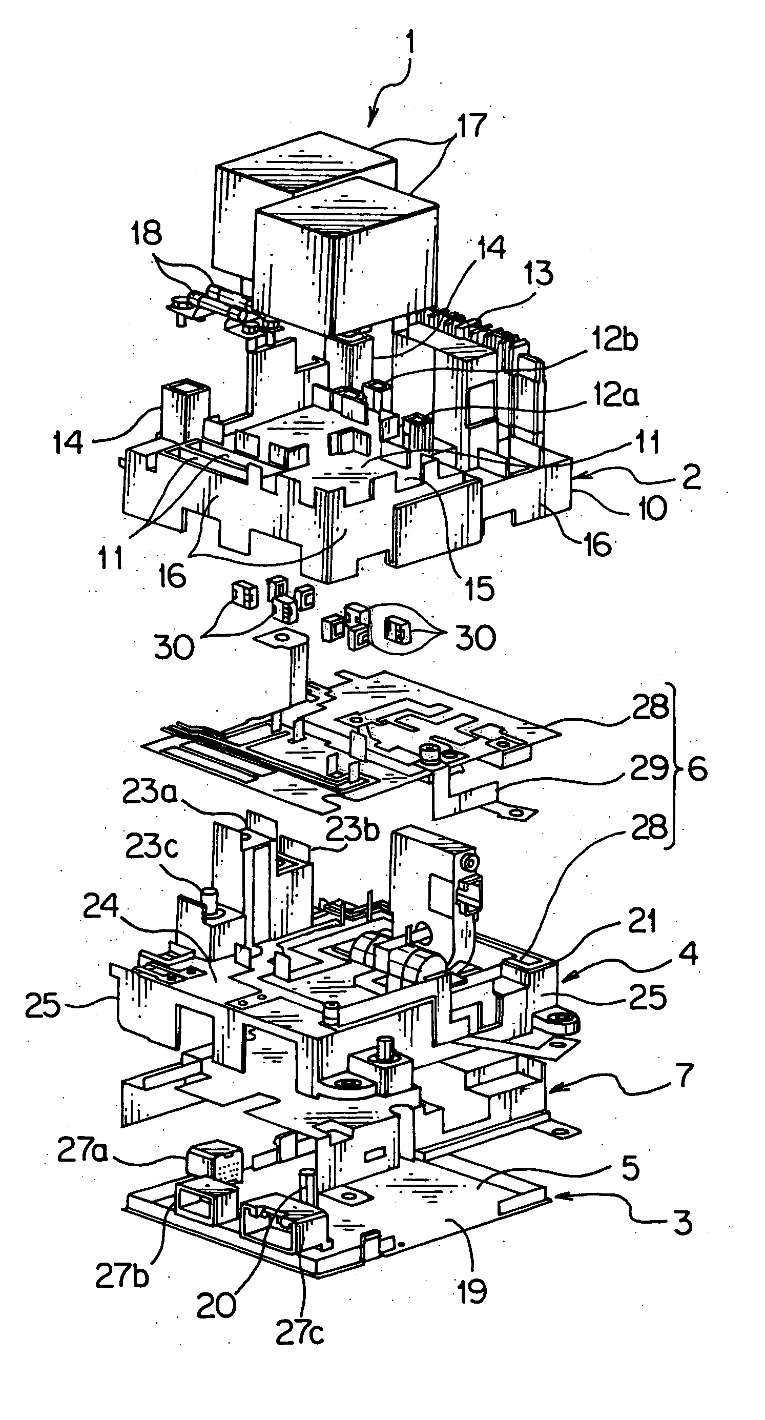
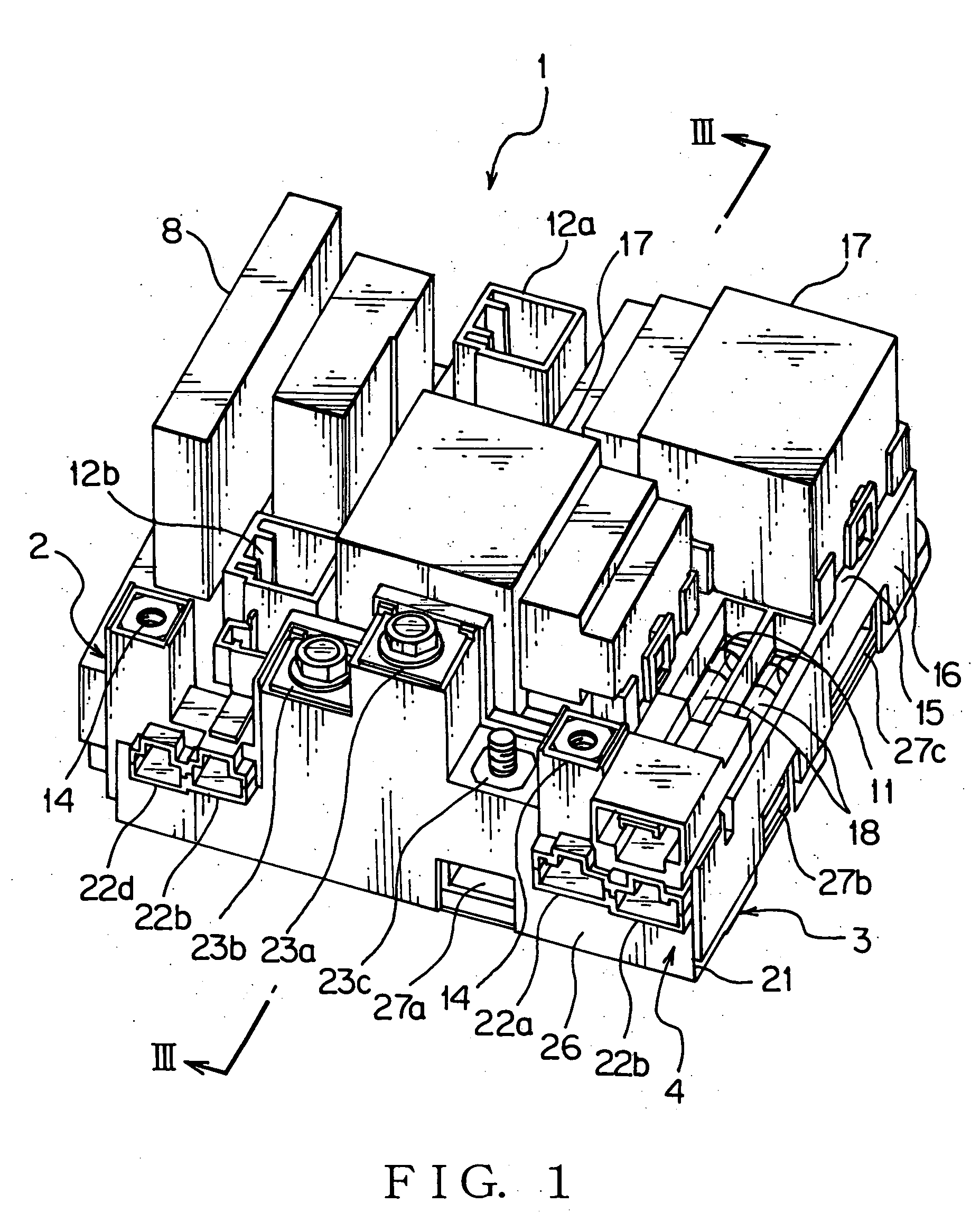
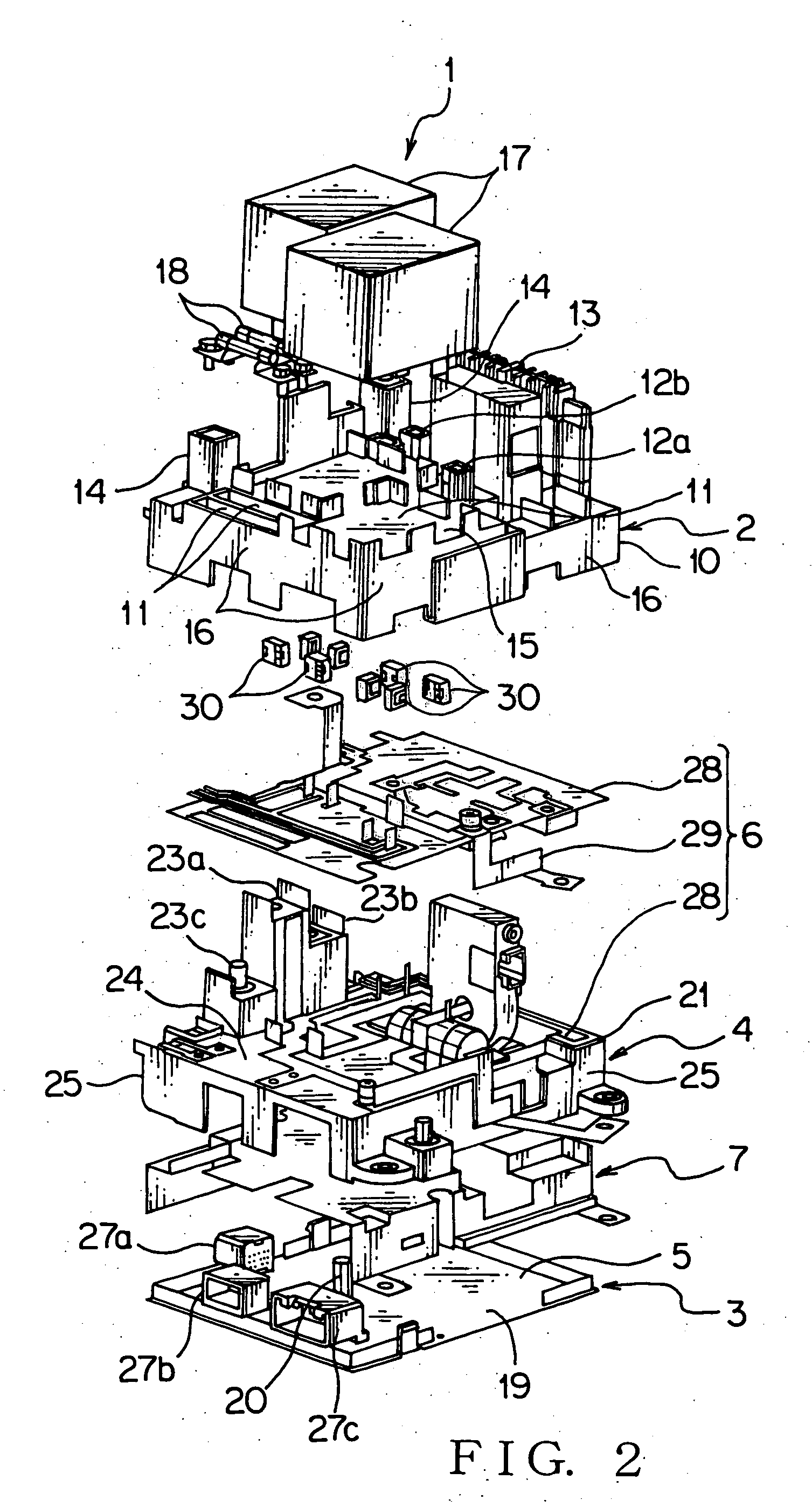
[0030] An electric connecting box 1 according the present invention will be described with reference to FIG. 1-4. The electric connecting box 1 shown in FIG. 1 is installed in a hybrid car, which can be driven both by an electric motor and an engine, as a vehicle so as to be mounted on a dash panel of the hybrid car.

[0031] As shown in FIG. 1, 2, the electric connecting box has an upper cover 2, a lower cover 3, a middle cover 4, a printed wire board 5 (shown in FIG. 2) as the first circuit unit, a wiring board 6 (shown in FIG. 2) as the second circuit unit, a shield plate 7 (shown in FIG. 2) and a service plug 8 (shown in FIG. 1). The upper cover 2 made of an insulating synthetic resin is provided with a bottom-opened box-shape cover body 10, a plurality of mounting portions 11 disposed on the cover body 10, a plurality of connectors 12a, 12b disposed in the cover body, a service plug mounting portion 13 and a terminal block 14.

[0032] The cover body 10 is formed integrally with a p...

third embodiment

[0066] In the third embodiment, the first struts 20, 34 abut on each other at the end surfaces thereof. According to the present invention, the first strut 20 may abut on the top wall 15 of the upper cover 2 and the second strut 34 may abut on the cover body 19 of the lower cover 3. In this case, the first strut 20 and the second strut 34 also support the force acting on the upper cover 2 along the arrows F1, F2, when the relay 17 is mounted. Therefore, the upper cover 2 can be prevented from approaching the lower cover 3. Thus, the upper cover 2 and the lower cover 3 can be prevented from breakage and the printed wire board 5 can be prevented from deterioration of reliability.

[0067] According to this embodiment, when the relay 17 is mounted, the first strut 20 and the second strut 34 prevent the upper cover 2 and the lower cover 3 from breakage. According to the present invention, when the fuse and a fusible link are mounted, the struts 20, 34 may prevent the upper cover 2 and the ...


PUM


Abstract

Preventing an electric connecting box having an upper cover and a lower cover, which can prevent the upper cover from approaching the lower cover over a limit when an electric component is mounted on the upper cover, the electric connecting box 1 is provided with an upper cover 2, a lower cover 3, a middle cover 4, a printed wire board 5, a wiring board 6 and a shield plat 7. The upper cover 2 is mounted on the lower cover 3. The lower cover 3 has a first strut 20 abutting on the shield plate 7. The first strut 20 supports the upper cover 2 through the shield plate 7 and the wiring board 6.

Description

[0001] The priority application Number Japan Patent Application No. 2003-364512 upon which this patent application is based is hereby incorporated by reference. BACKGROUND OF THE INVENTION [0002] 1. Field of the Invention [0003] This invention relates to an electric connecting box for mounting an electric component such as a relay and a fuse. [0004] 2. Description of the Related Art [0005] Generally, a various electric connecting box is installed in for example an electric vehicle, including a hybrid car, for connecting electrically a battery and an inverter. The electric connecting box has a fuse, a relay and a bus bar, and is called as a junction block, a fuse block or a relay box. [0006] The aforesaid electric connecting box includes an upper cover, a lower cover being mounted to the upper cover and a wiring board as a circuit unit to be received between the upper cover and the lower cover. An electric component, such as a fuse and a relay, is mounted on the upper cover. Then, th...

Claims


Application Information

Patent Timeline
Patent Type & Authority Applications(United States)
IPC IPC(8): B60R16/02H05K5/03B60R16/023H02G3/08H02G3/16
CPCB60R16/0238
Inventor IKEDA, TOMOHIROMIYAZAKI, YASUTAKAWATANABE, KOTSUCHIYA, TAKENORIMATSUMOTO, SHIGEKI
Owner YAZAKI CORP
Why Eureka
Try Eureka