Illumination device, display device, and television receiver apparatus

a technology of display device and display device, which is applied in the direction of lighting support device, television system, instruments, etc., can solve the problems of linear light source lighting failure and risk of liquid crystal display device display quality loss, and achieve uniform illumination luminance, constant distance, and the effect of limiting the distance between the linear light source and the chassis

Inactive Publication Date: 2011-01-06
SHARP KK
View PDF10 Cites 4 Cited by
  • Summary
  • Abstract
  • Description
  • Claims
  • Application Information

AI Technical Summary

Benefits of technology

[0008]The present invention has been made based on the circumstances such as described above, and an object thereof is to provide an illumination device with superior uniformity of illumination luminance distribution by maintaining a constant distance between a light source and a chassis. Another object of the present invention is to provide a display device including such an illumination device, and a television receiver apparatus including such a display device.MEANS FOR SOLVING THE PROBLEMS
[0010]Such a configuration enables a constant distance to be maintained between the linear light source and the chassis while hardly forming dark areas on the linear light source, and notably restricts the linear light source and the chassis from approaching each other.
[0012]According to a configuration of the present invention, a spacer is provided interposed between the linear light source and the chassis in order to maintain a constant distance between the linear light source and the chassis. Since the spacer suppresses the linear light source and the chassis from approaching each other by being interposed between the linear light source and the chassis, the spacer does not cover the linear light source. Therefore, dark areas are less likely to be present at the linear light source. In addition, by providing the spacer at a position overlapping the linear light source in plan view, a shadow is less likely to be created by the outputted light from the linear light source. Therefore, the distance between the linear light source and the chassis can be restricted from falling below a predetermined distance without dark areas on the linear light source. As described above, by providing the spacer, a situation where the linear light source and the chassis excessively approach each other, which must be particularly avoided, can be suppressed. As a result, a uniform illumination luminance distribution free of luminance unevenness can be realized while hardly forming dark areas on the linear light source.

Problems solved by technology

Therefore, a deflection of the linear light source due to its own weight or a partial warpage of the linear light source due to insufficient strength of the chassis may cause a variance in the distances between the respective linear light sources and the chassis and differences in outputted light intensity per linear light source and may create a risk of a display quality loss of the liquid crystal display device.
In particular, when the linear light source and the chassis become too close to each other such that a distance therebetween equals or falls below a predetermined distance, an increase in leakage may cause lighting failure of the linear light source.

Method used


Image

  • Illumination device, display device, and television receiver apparatus
  • Illumination device, display device, and television receiver apparatus
  • Illumination device, display device, and television receiver apparatus

Examples


first embodiment

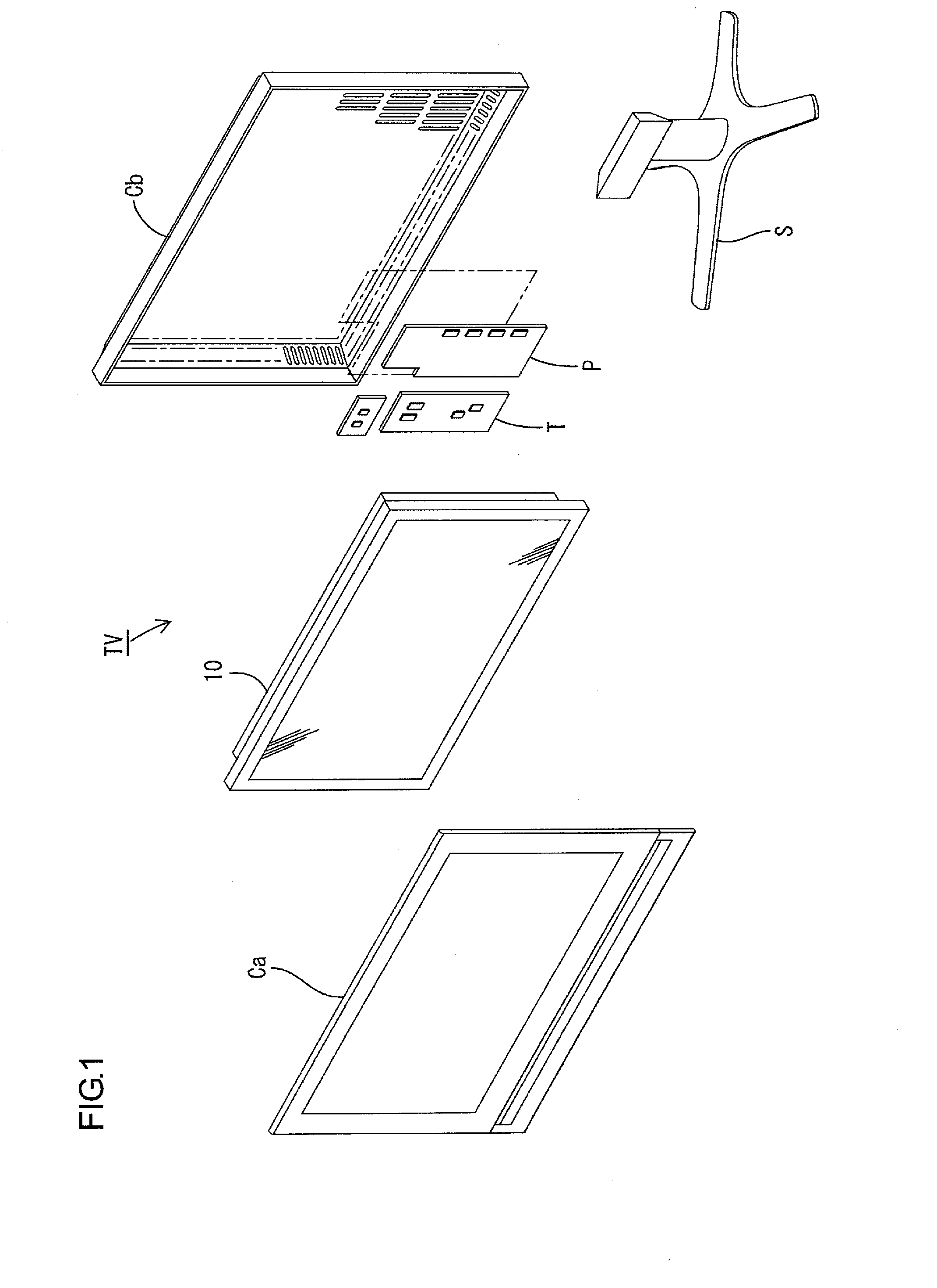
[0037]A first embodiment of the present invention will be described with reference to FIGS. 1 to 9. First, a configuration of a television receiver apparatus TV including a liquid crystal display device 10 will be described with reference to FIGS. 1 to 6.

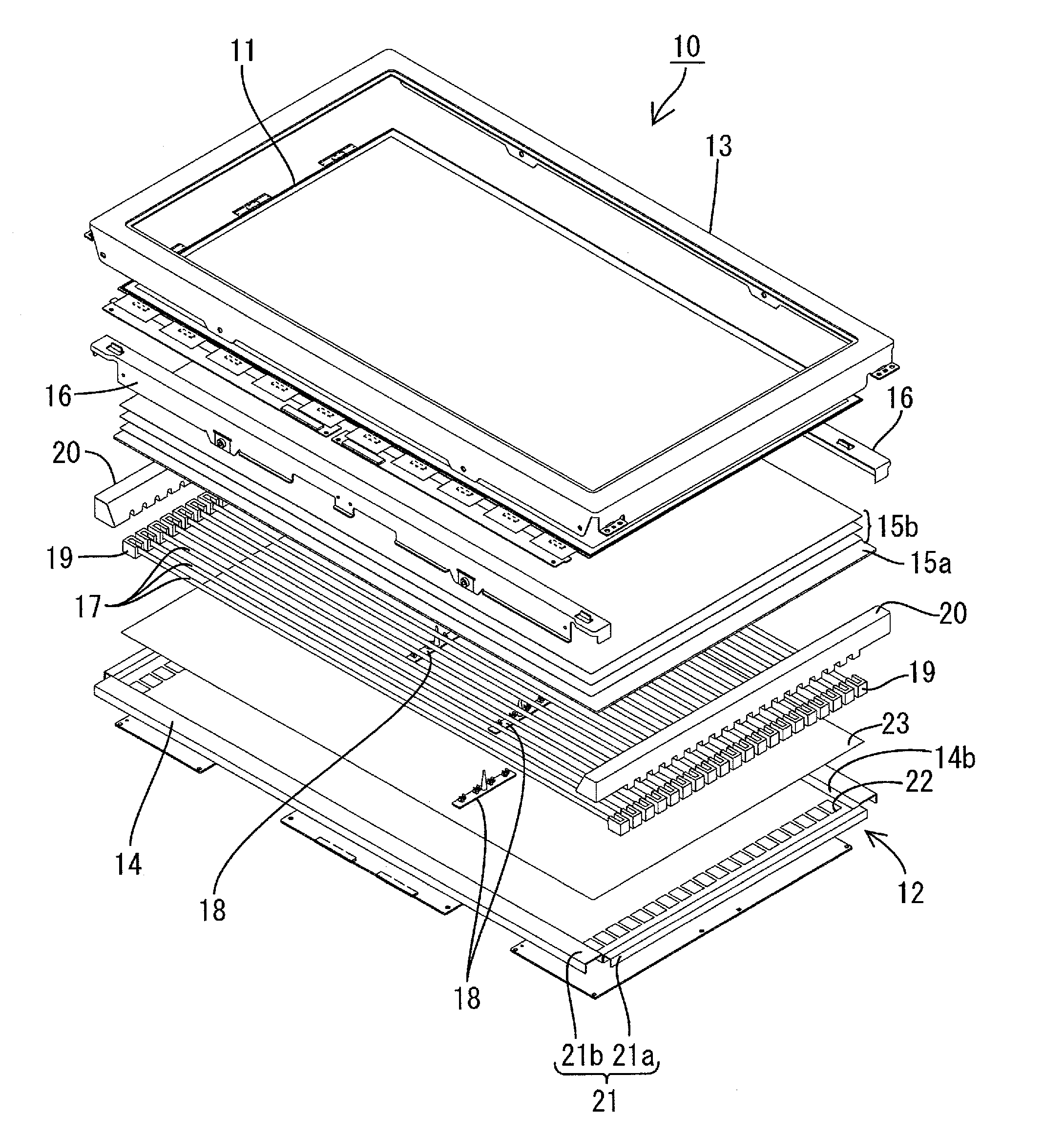
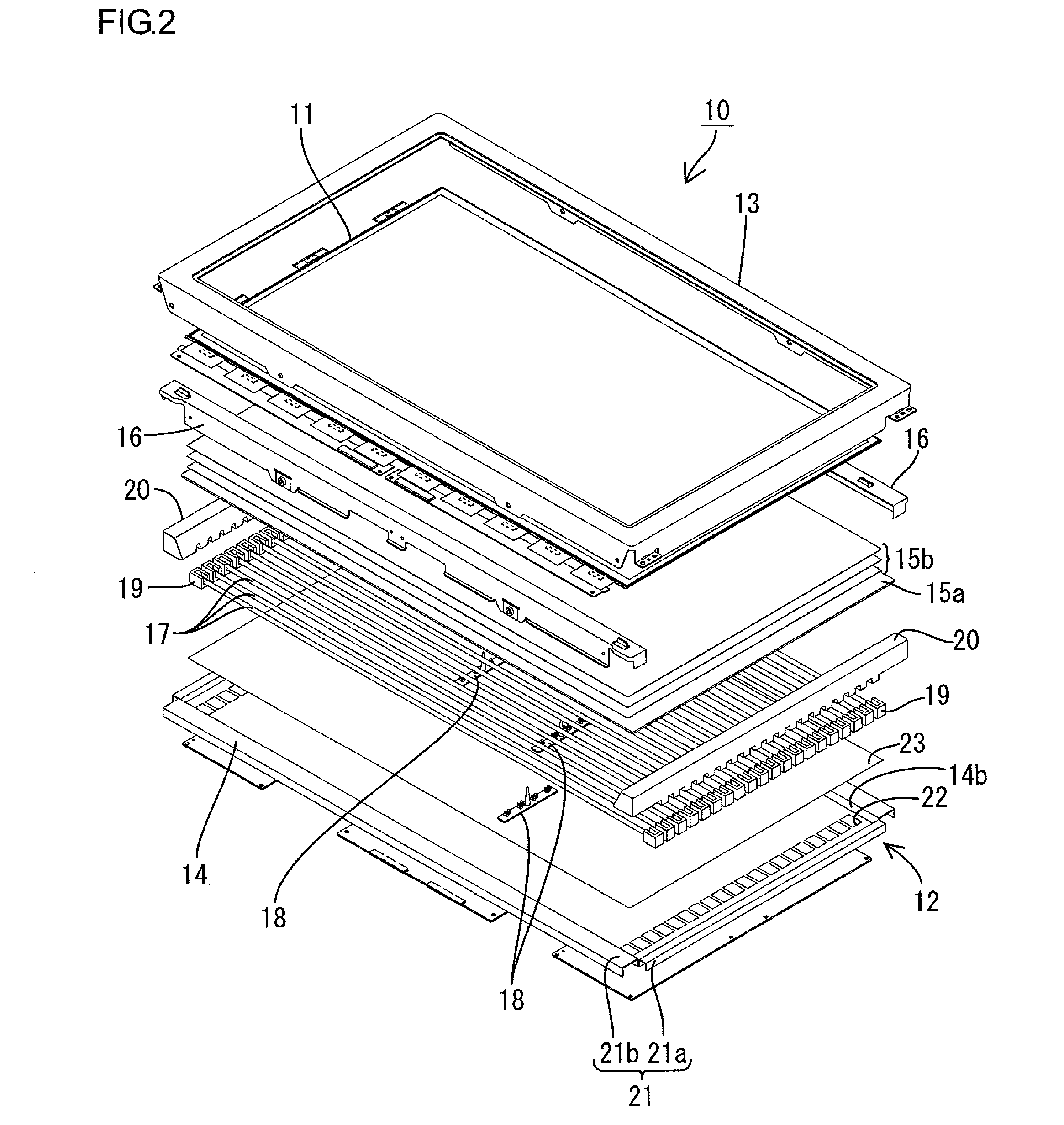
[0038]FIG. 1 is an exploded perspective view illustrating a schematic configuration of the television receiver apparatus according to the present embodiment. FIG. 2 is an exploded perspective view illustrating a schematic configuration of a liquid crystal display device included in the television receiver apparatus illustrated in FIG. 1. FIG. 3 is a cross-sectional view illustrating a cross-sectional configuration in a short-side direction of the liquid crystal display device illustrated in FIG. 2. FIG. 4 is a cross-sectional view illustrating a cross-sectional configuration in a long-side direction of the liquid crystal display device illustrated in FIG. 2. FIG. 5 is a cross-sectional view illustrating a configuration of a lamp cli...

second embodiment

[0088]Next, a second embodiment of the present invention will be described with reference to FIGS. 10 and 11. In the present second embodiment, a configuration will be presented where the shape of the spacer has been modified. Otherwise, the present second embodiment is the same as the embodiment described above. Like parts to the embodiment described above will be denoted using like reference characters and redundant descriptions thereof will be omitted.

[0089]As illustrated in FIG. 10, a spacer sheet 40B is configured such that a plurality of spacers 41B with approximately semicircular column shapes is juxtaposed on a base plate sheet 42B. In the spacer 41B, an end part opposite a cold cathode tube 17 is formed as a striation 43B. The spacer 41B has peripheral surfaces 44B and 45B that convexly curve from the striation 43B to the base plate sheet 42B. The spacers 41B are aligned so that the striation 43B conforms to a short-side direction of the base plate sheet 42B (spacer sheet 4...

third embodiment

[0091]Next, a third embodiment of the present invention will be described with reference to FIGS. 12 and 13. In the present third embodiment, a configuration will be presented where the shape of the spacer has been further modified. Otherwise, the present third embodiment is the same as the embodiments described above. Like parts to the embodiments described above will be denoted using like reference characters and redundant descriptions thereof will be omitted.

[0092]As illustrated in FIG. 12, a spacer sheet 40C is configured such that a plurality of approximately wave-shaped spacers 41C whose end surfaces opposite a cold cathode tube 17 are depressed in an arc is juxtaposed on a base plate sheet 42C. In the spacer 41C, the end surface opposite the cold cathode tube 17 is formed as a depressed ridge 43C depressed in an arc. The spacer 41C has curved surfaces 44C and 45C that concavely curve and which form ridge-like shapes that spread from the depressed ridge 43C to the base plate s...


PUM

PropertyMeasurementUnit
diameteraaaaaaaaaa
distanceaaaaaaaaaa
distanceaaaaaaaaaa

Abstract

An illumination device 12 according to the present invention includes a linear light source 17, a chassis 14 that houses the linear light source 17, and a spacer 41 that is provided between the linear light source 17 and the chassis 14 so as to separate the linear light source 17 from the chassis 14. The spacer 41 is arranged under the linear light source 17 on the chassis 14 when viewed in plan. Since the spacer 41 is provided between the linear light source 17 and the chassis 14 so as to maintain a distance therebetween over a predetermined distance, the spacer 41 does not overlap the linear light source 17. Therefore, dark areas are less likely to be present on the linear light source 17 and thus uniformity of illumination luminance distribution can be ensured.

Description

TECHNICAL FIELD[0001]The present invention relates to an illumination device, a display device, and a television receiver apparatus.BACKGROUND ART[0002]For example, since a liquid crystal panel used in a liquid crystal display device such as a liquid crystal television is not self-luminous, such a liquid crystal panel separately requires a backlight unit as an illumination device. Such a backlight unit is intended to be installed on a rear side (a side opposite to a display surface) of the liquid crystal panel and, for example, includes: a metallic chassis having an opened surface on the liquid crystal panel-side; and a large number of linear light sources (for example, cold cathode tubes) housed in the chassis.[0003]The aforementioned linear light source leaks light, albeit only slightly, to the chassis during lighting. The amount of leakage is inversely proportional to a distance between the linear light source and the chassis. Therefore, a deflection of the linear light source du...

Claims


Application Information

Patent Timeline
Patent Type & Authority Applications(United States)
IPC IPC(8): H04N5/64F21V21/00F21S4/00F21V7/00G02F1/13357G02F1/1335
CPCG02F1/133604G02F1/133611G02F1/133608
Inventor YAMAMOTO, KAORI
Owner SHARP KK
Why Eureka
Try Eureka