Protective Helmet and Screen

a protective helmet and screen technology, applied in the field of protective helmets, can solve the problems of increasing the risk of poor assembly, affecting the protection of the wearer, and affecting the effect of the screen,

Active Publication Date: 2015-02-12
MSA PRODION FRANCE
View PDF5 Cites 2 Cited by
  • Summary
  • Abstract
  • Description
  • Claims
  • Application Information

AI Technical Summary

Benefits of technology

[0017]In a further preferred and non-limiting embodiment, the screen includes a spigot projecting toward the inside, which is suitable for coming to a stop above one part of the ring in order to hold the screen in the high position, and which can go beyond the part downward, upon the manual action of a user. Thus, the voluntary passage beyond this part of the ring leads to locking or unlocking the screen. However, when the screen is in the high position, it cannot go to the low position in an untimely manner, which could occur simply by its weight or upon the action of a moderate shock, such as that which could be produced when a fireman wearing the helmet jumps from a truck.
[0018]In addition, the ring can include an element projecting toward the outside, configured to interact with a support zone arranged on the screen when the screen is moved from its low position and close to the face to its high position, in such a way as to cause, during this movement, the pivoting of the principal part of the screen about the second pivot axis, in the direction of moving away from the face. This arrangement allows rubbing of the screen against the ring to be avoided, which would risk scratching it. It is to be noted that this projection and the aforementioned part of the ring can be one and the same element.

Problems solved by technology

However, in certain situations, the screen cannot protect the wearer effectively, particularly from elements that could be thrown from below in the direction of the face, entering the helmet through the relatively large space existing between the face and the screen.
However, the system for assembling the screen described in this document involves a certain number of pieces that risk being lost, which complicates the assembly and increases the risks of poor assembly.
Moreover, this system is not sufficiently robust, because it is difficult to move the screen between its different positions in either a fluid or precise manner.

Method used


Image

  • Protective Helmet and Screen
  • Protective Helmet and Screen
  • Protective Helmet and Screen

Examples


Embodiment Construction

[0042]For purposes of the description hereinafter, the terms “end”, “upper”, “lower”, “right”, “left”, “vertical”, “horizontal”, “top”, “bottom”, “lateral”, “longitudinal” and derivatives thereof shall relate to the invention as it is oriented in the drawing figures. It is to be understood that the invention may assume various alternative variations, except where expressly specified to the contrary. It is also to be understood that the specific devices and processes illustrated in the attached drawings, and described in the following specification, are simply exemplary embodiments of the invention. Hence, specific dimensions and other physical characteristics related to the embodiments disclosed herein are not to be considered as limiting.

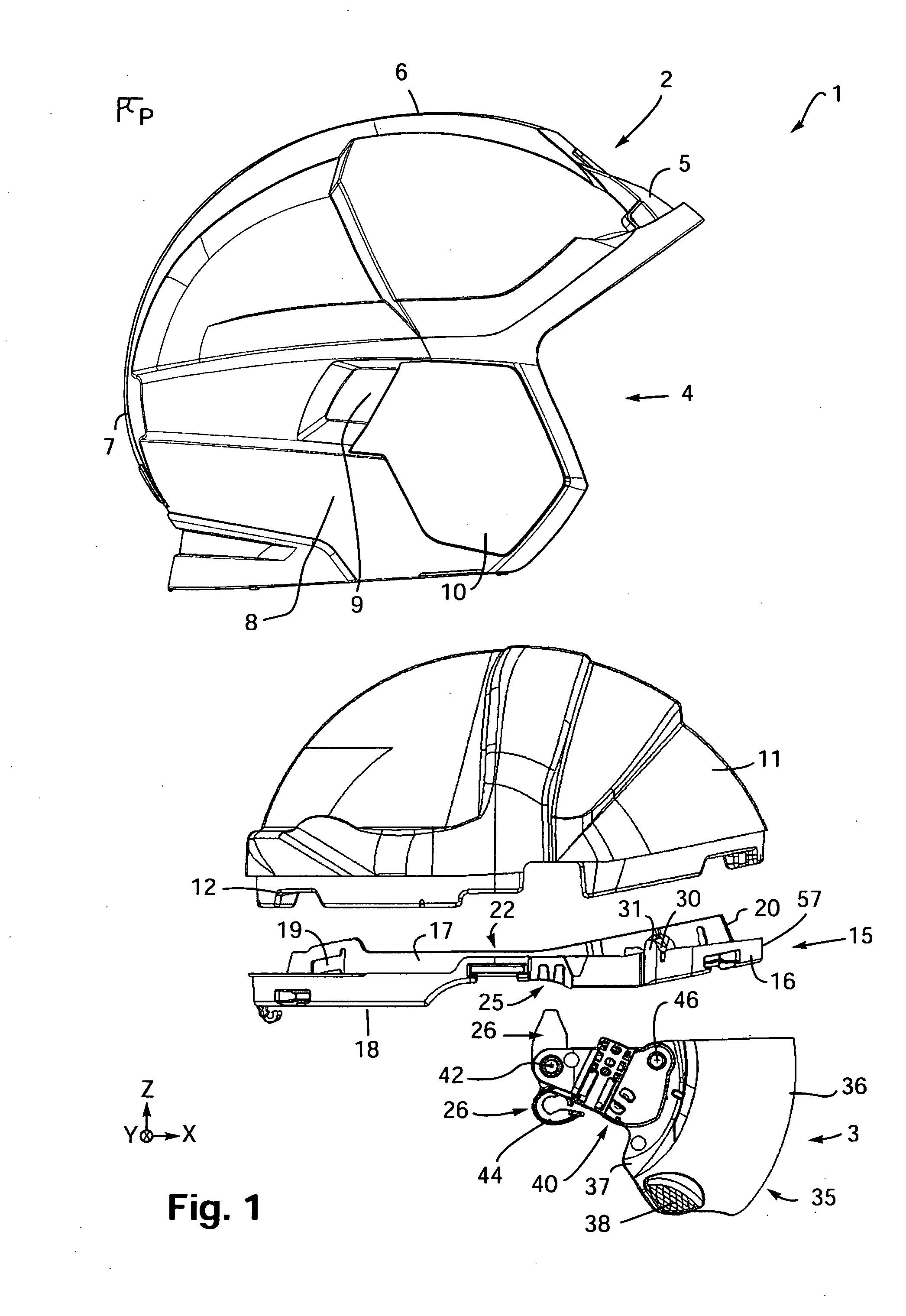
[0043]The present invention relates to a protective helmet and screen, as illustrated in certain preferred and non-limiting embodiments in FIGS. 1-15.

[0044]In one preferred and non-limiting embodiment, and as illustrated in FIG. 1, provided is a he...


PUM


Abstract

A screen for a safety helmet, including a principal part having at least one wing with at least one linkage piece mounted thereto, where the linkage piece includes: a first arrangement for connecting the screen to the shell and configured to facilitate pivoting of the at least one linkage piece relative to the shell, such that the screen is moveable between a low position, in which the screen is substantially covering the face opening, and a high position, in which the face opening is substantially clear; and a second arrangement for connecting to the at least one wing and configured to facilitate the pivoting of the principal part relative to the at least one linkage piece; wherein the principal part is moveable relative to the at least one linkage piece between a position substantially away from and a position substantially close to the face opening.

Description

BACKGROUND OF THE INVENTION[0001]1. Field of the Invention[0002]The present invention relates generally to protective helmets for use in various situations and environments, and in particular to a protective helmet equipped with a view or ocular screen, a structure and arrangement for attachment to an internal portion of the external shell of a protective helmet or safety helmet.[0003]2. Description of the Related Art[0004]In various industries and environments, certain people, e.g., firemen, are required to wear a helmet for their protection. A helmet typically includes a shell for head protection, which includes a face opening opposite the wearer's face and a viewscreen that can be placed in front of the user's eyes. The viewscreen is generally pivotally mounted in relation to the shell about a transverse axis between a low position, in which the screen is extended relative to the face opening, and a high position, in which the face opening is substantially clear. Thus, the wearer...

Claims


Application Information

Patent Timeline
Patent Type & Authority Applications(United States)
IPC IPC(8): A42B3/22
CPCA42B3/221A42B3/222A42B3/04
Inventor GUAY, LOUISMICHEL, PASCAL
Owner MSA PRODION FRANCE
Why Eureka
Try Eureka