
Automobile car body front construction and method of assembling car body front

Inactive Publication Date: 2005-04-28
NISSAN MOTOR CO LTD
View PDF17 Cites 50 Cited by
  • Summary
  • Abstract
  • Description
  • Claims
  • Application Information

AI Technical Summary

Benefits of technology

[0006] According to such a constitution, the head-lamp units can be positionally adjusted to and attached to the front fenders on the basis of the latter, respectively, thereby enabling to uniformalize the clearances and offset-amounts in parting portions between the head-lamp units and the front ends of the front fenders, respectively, to thereby further improve the external appearance.
[0027] Further, it becomes possible to avoid interference of the head-lamp units with the front fenders upon abutting the radiator core support panel to the front ends of the front side members from the vehicular front, thereby allowing to further facilitate the mounting operation.

Problems solved by technology

However, it is probable that the clearances, offset-amounts and the like in parting portions between the head-lamp units and the front ends of front fenders become non-uniform to thereby deteriorate the external appearance, such as due to a cumulation of mounting precision errors between the radiator core support panel and the front side members and front fenders, and of mounting precision errors between the radiator core support panel and the head-lamp units.

Method used


Image

  • Automobile car body front construction and method of assembling car body front
  • Automobile car body front construction and method of assembling car body front
  • Automobile car body front construction and method of assembling car body front

Examples


first embodiment

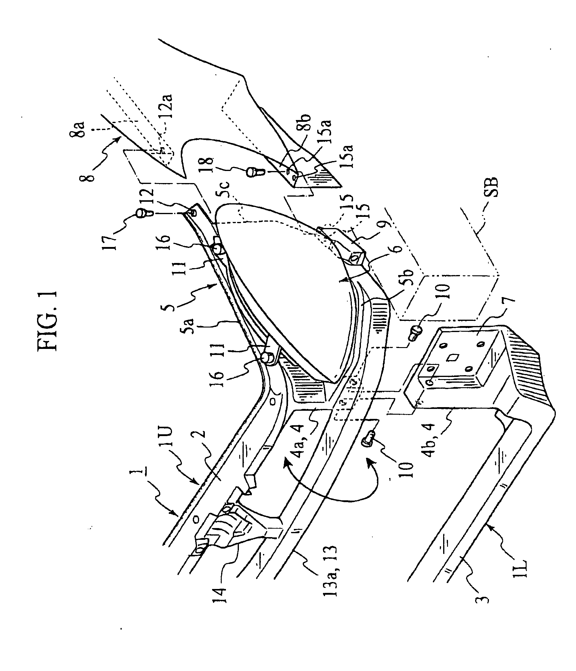
[0040] (First Embodiment)

[0041] In FIG. 1, reference numeral 1 designates a radiator core support panel made of a plastic material and constituting a frontmost part of a vehicular body (i.e., front end of vehicular body), and this panel 1 comprises: an upper rail 2 and a first cross-member 3 arranged one above the other, and both extending in a vehicular widthwise direction; pillar portions 4 for interconnecting the upper rail 2 and first cross-member 3 at both vehicular widthwise sides thereof, respectively; and side portions 5 bulgedly provided at the vehicular widthwise outsides of the pillar portions 4, respectively, so as to mount head-lamp units 6 onto the side portions 5 themselves, respectively.

[0042] Each side portion 5 comprises an upper frame 5a formed integrally with and as an extension of the upper rail 2, a lower frame 5b laterally bulged from and provided integrally with the pillar portion 4, and a side frame 5c for interconnecting the upper frame 5a and lower frame ...

second embodiment

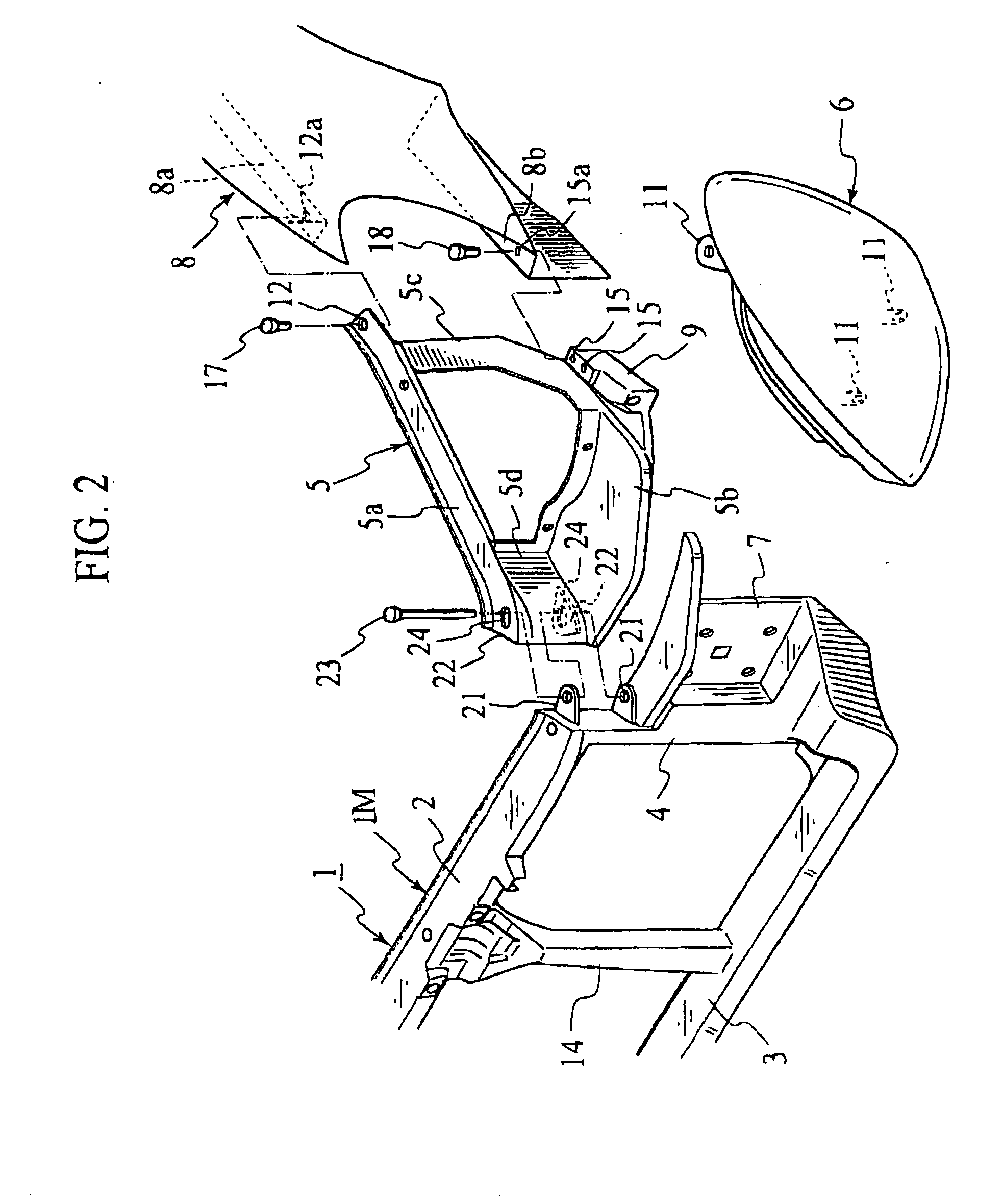
[0058] (Second Embodiment)

[0059]FIG. 2 shows a second embodiment of the present invention including a radiator core support panel 1 divided into: a main portion 1M comprising an upper rail 2, a first cross-member 3, pillar portions 4, fastening seat portions 7, and a hood lock stay 14, which are formed integrally with one another such as by injection molding; and side portions 5 integrally formed themselves such as by injection molding, and coupled to the main portion 1M pivotably in the vehicular widthwise direction and slidably in the vehicular fore-and-aft direction.

[0060] In this embodiment, the hood lock stay 14 is vertically formed across and integrally with vehicular widthwise central portions of the upper rail 2 and first cross-member 3.

[0061] The main portion 1M is integrally formed with a pair of upper and lower bracket supporting seats 21 at an upper side surface of each pillar portion 4, while each side portion 5 has a coupling base 5d positioned at a vehicular widthwi...

third embodiment

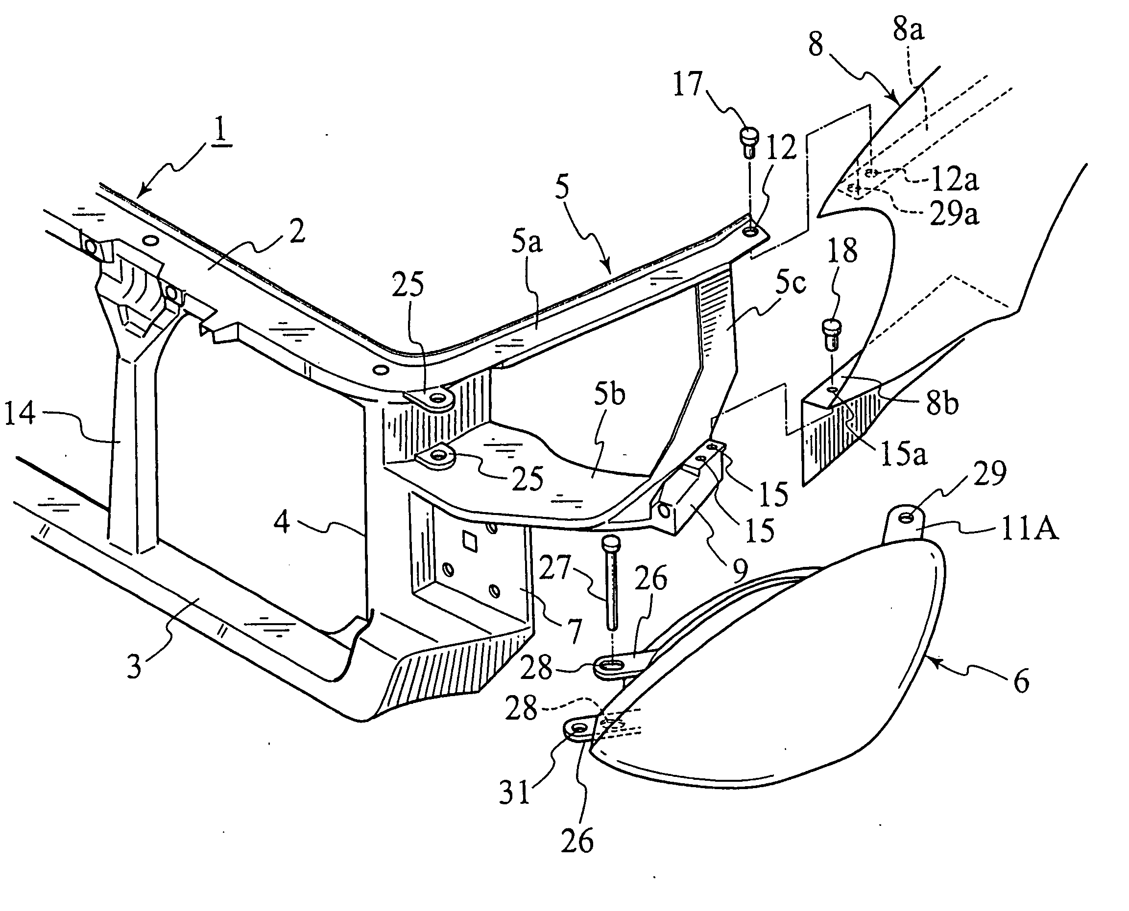
[0069] (Third Embodiment)

[0070]FIG. 3 shows a third embodiment of the present invention including a radiator core support panel 1 integrally formed of an upper rail 2, a first cross-member 3, pillar portions 4, side portions 5, fastening seat portions 7 and a hood lock stay 14 such as by injection molding, and each side portion 5 is movably mounted with a head-lamp unit 6.

[0071] Also in this embodiment, the hood lock stay 14 is vertically formed across and integrally with vehicular widthwise central portions of the upper rail 2 and first cross-member 3.

[0072] Each side portion 5 comprises an upper frame 5a and a lower frame 5b having forming bases at vehicular widthwise insides thereof integrally formed with bracket supporting seats 25, respectively, while each head-lamp unit 6 includes a vehicular widthwise inside portion protrudedly provided with a pair of upper and lower brackets 26, such that these brackets 26 are coupled to the bracket supporting seats 25 via pins 27, respect...


PUM


Abstract

In a front body structure of a vehicle and an assembling method of a front body of a vehicle, head-lamp units (6) disposed at both vehicular widthwise sides of a radiator core support panel (1), respectively, are made into movable structures positionally adjustable to front fenders (8), thereby allowing to attach the head-lamp units (6) to the front fenders (8) on the basis of the latter, respectively, and to uniformalize clearances, offset-amounts and the like in parting portions between the head-lamp units (6) and the front ends of the front fenders (8).

Description

TECHNICAL FIELD [0001] The present invention relates to a front body structure of a vehicle and an assembling method of a front body of a vehicle. BACKGROUND ART [0002] Recently, in order to simplify an assembling process of vehicular bodies and to automatize the mounting operations, for example, it has been proposed to mount head-lamp units, a front bumper and the like onto a radiator core support panel to thereby constitute a so-called front-end module as a sub-assembly, and to mount the front-end module onto a front body of a vehicle in a vehicular body assembling line (see Japanese Patent Application Laid-Open Publication Nos. H11-20543 and H1148856). [0003] However, it is probable that the clearances, offset-amounts and the like in parting portions between the head-lamp units and the front ends of front fenders become non-uniform to thereby deteriorate the external appearance, such as due to a cumulation of mounting precision errors between the radiator core support panel and t...

Claims


Application Information

Patent Timeline
IPC IPC(8): B60Q1/04B62D25/08
CPCB60Q1/0425B62D25/084B60Q1/045B60Q1/0433
Inventor KISHIKAWA, SHOUICHIFUROKOSHI, KENJI
Owner NISSAN MOTOR CO LTD
Features
  • Generate Ideas
  • Intellectual Property
  • Life Sciences
  • Materials
  • Tech Scout
  • Unparalleled Data Quality
  • Higher Quality Content
  • 60% Fewer Hallucinations
Learn More