Security viewing apparatus and method

a technology for security viewing and equipment, applied in the direction of mountings, optics, magnifying glasses, etc., can solve the problems of inconvenient installation of camera systems, inconvenient installation of camera equipment, and inability to provide an expanded view of the outside of the door. , to achieve the effect of convenient installation

Inactive Publication Date: 2005-04-28
PURSER BRIAN
View PDF3 Cites 1 Cited by
  • Summary
  • Abstract
  • Description
  • Claims
  • Application Information

AI Technical Summary

Benefits of technology

[0002] Therefore, it is an object of the invention to provide a s

Problems solved by technology

While very simple in nature, it does not provide an expanded view of the outside of the door.
In addition, the peep hole is not very practical for someone of shorter stature to use due to its non-adjustable nature.
However, the camera system requires e

Method used


Image

  • Security viewing apparatus and method
  • Security viewing apparatus and method
  • Security viewing apparatus and method

Examples


Embodiment Construction

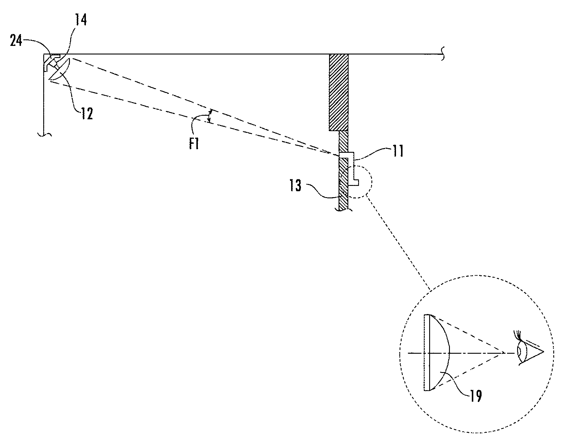
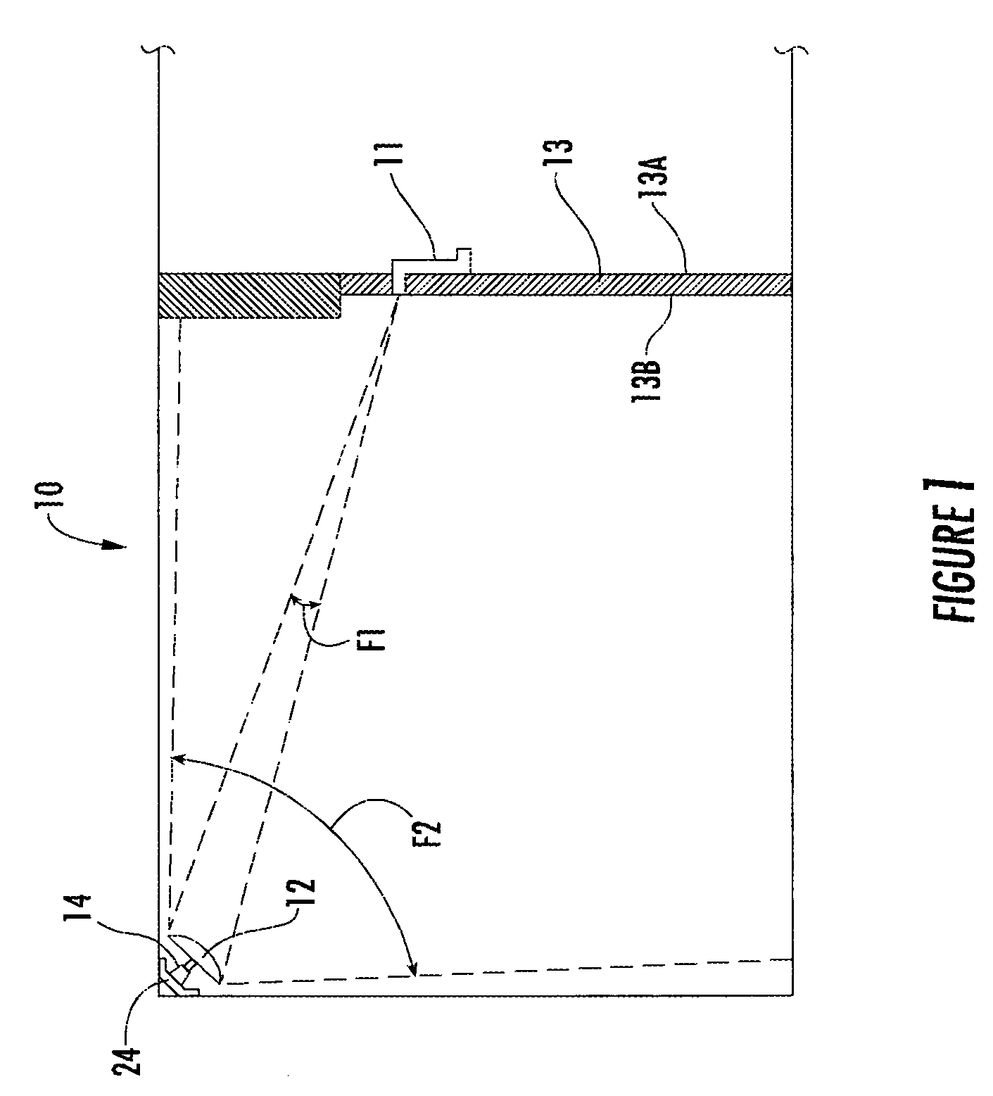
[0041] Referring now specifically to the drawings, a security viewing apparatus according to the present invention is illustrated in FIG. 1 and shown generally at reference numeral 10. The particular embodiment shown is a relationship of a viewing device 11 producing a first field of view F1 and a convex reflective surface 12 producing a second field of view F2, which is substantially greater than the first field of view F1. The viewing device 11 and convex reflective surface 12 are positioned in a spaced-apart relationship to provide a view of a selected area outside of a vertical surface 13. The vertical surface could be a door or a wall.

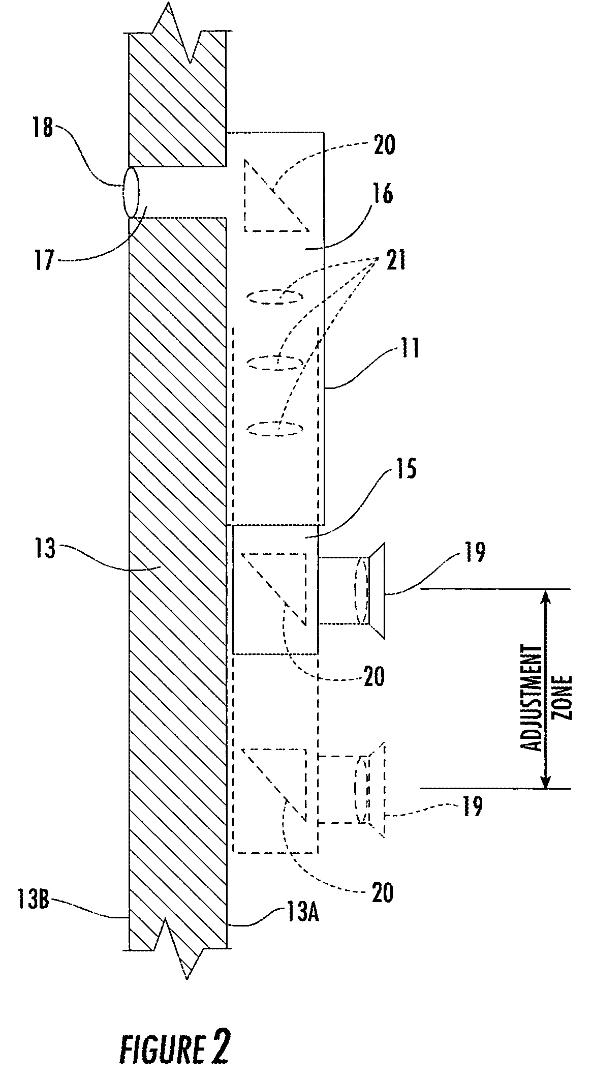
[0042] Referring now to FIGS. 2 and 3, the viewing device 11 includes an inner vertical tube 15 mounted inside of an outer vertical tube 16 for allowing a telescopic adjustment in a vertical direction, and a horizontal tube 17 attached to a top end of the outer vertical tube. The inner vertical tube 15 is adjustable in the vertical direction slid...


PUM


Abstract

A security viewing apparatus for residential or commercial use. The security viewing apparatus has a viewing device and a reflective surface. The viewing device is mounted to the inside of a door and includes an inner vertical tube, an outer vertical tube, a horizontal tube attached to the top of the outer vertical tube, an eyepiece attached to the lower end of the inner vertical tube, and a plurality of lenses and a plurality of reflective devices inside the inner and outer vertical tubes. The reflective surface is mounted to a surface opposite the outside of a door. The reflective surface is convex and has a rectangular shape. When used together, the combination of the viewing device and reflective surface provides an expanded viewing zone of the outside of the door, enhancing the users safety and security.

Description

TECHNICAL FIELD AND BACKGROUND OF THE INVENTION [0001] This invention relates to a security viewing apparatus for residential or commercial use to provide users with an expanded view of the outside of a door, enhancing the security and safety of the user. Security viewing devices presently take many forms. One such device is a peep hole mounted through a door. While very simple in nature, it does not provide an expanded view of the outside of the door. The peep hole only shows what is standing right in front of it, allowing someone to avoid detection by simply kneeling down or moving to the side. The peep hole has no adjustment for focus or magnification. In addition, the peep hole is not very practical for someone of shorter stature to use due to its non-adjustable nature. Another such device is a camera system. This device provides a detailed and expanded view of the outside of the door, allowing the user to adjust both the focus and magnification. However, the camera system requi...

Claims


Application Information

Patent Timeline
IPC IPC(8): G02B13/06
CPCG02B13/06
Inventor PURSER, BRIAN
Owner PURSER BRIAN
Why Eureka
Try Eureka