

Optical transceiver module with improved DDIC and methods of use
- Summary
- Abstract
- Description
- Claims
- Application Information
AI Technical Summary
Benefits of technology
Problems solved by technology
Method used
Image

Examples
Example
DETAILED DESCRIPTION OF THE DRAWINGS
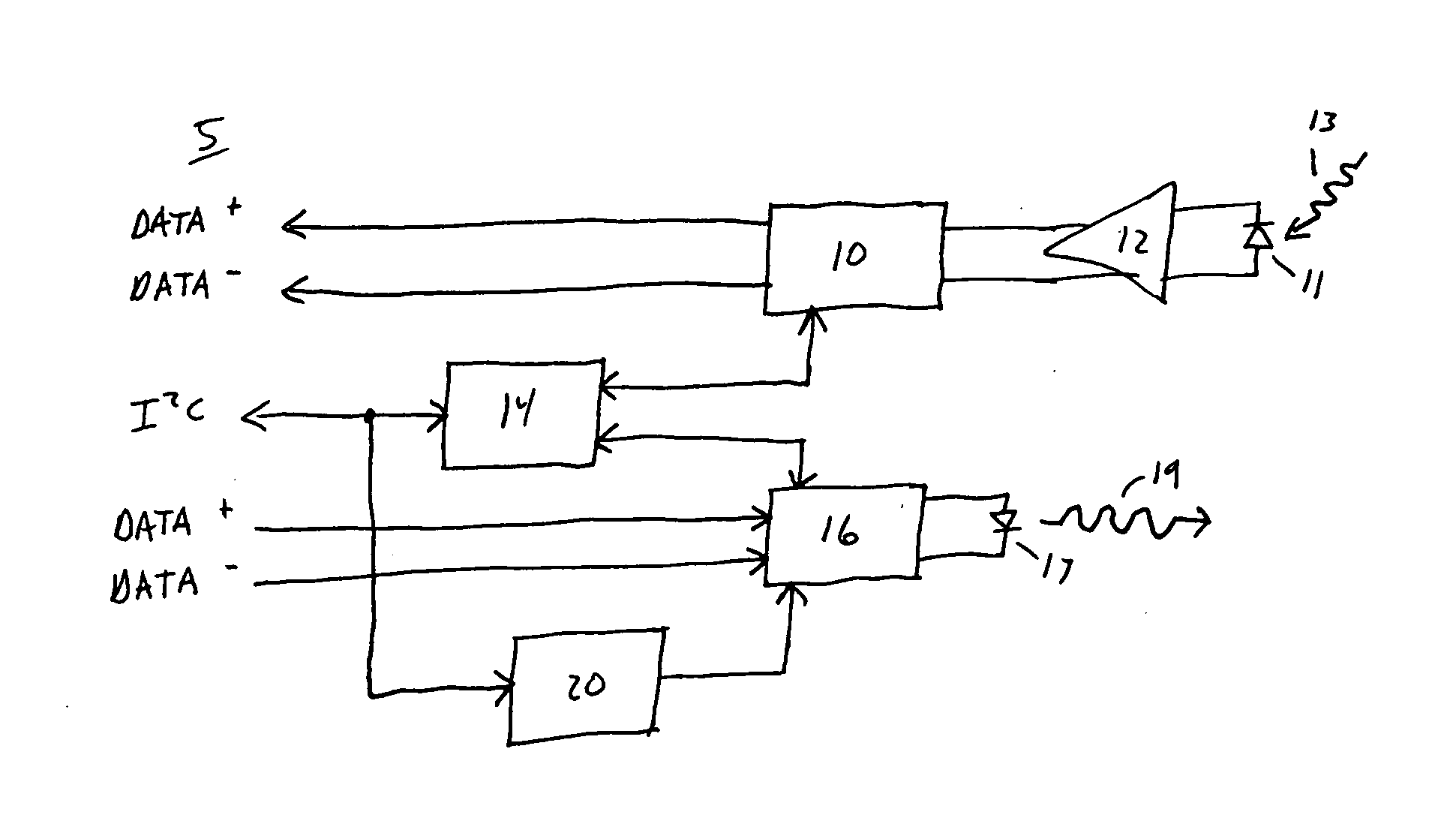
[0018] Turning now to FIG. 1, a simplified block diagram of an optical transceiver 5, illustrates functions typically performed in a fiber optic module. Transceiver 5 is provided for purposes of explanation of functions and not as a prior art device. It will be understood, however, that the functions of optical transceiver 5 can be performed in other types of optoelectronic modules wherein it is desired to convert an optical signal to an electrical signal or vice versa. The transceiver illustrated in FIG. 1 represents a standard small form factor 8472 (hereinafter referred to as “SFF-8472”), Revision 9.0 digital diagnostic solution. However, it will be understood that the illustration of SFF-8472 in this embodiment is for illustrative purposes only and that other standards could be used. These fiber optic modules are typically designed for single mode operation up to 2.5 Gbps. Further, these modules typically operate at a nominal wavelength of 13...
PUM
 Abstract
Description
Claims
Application Information