Cooling system for an electronic component

a technology of electronic components and cooling systems, applied in the field of computer sub-assembly, can solve the problems of general consumption of current and increased heat generation

Inactive Publication Date: 2005-05-05
TAHOE RES LTD
View PDF5 Cites 88 Cited by
  • Summary
  • Abstract
  • Description
  • Claims
  • Application Information

AI Technical Summary

Problems solved by technology

As semiconductor devices, such as processors, operate at continually higher data rates and higher frequencies, they generally consume greater current and produce more heat.
A semiconductor device such as a processor does not generate heat uniformly so that hot spots are created in certain areas.

Method used


Image

  • Cooling system for an electronic component
  • Cooling system for an electronic component
  • Cooling system for an electronic component

Examples


Embodiment Construction

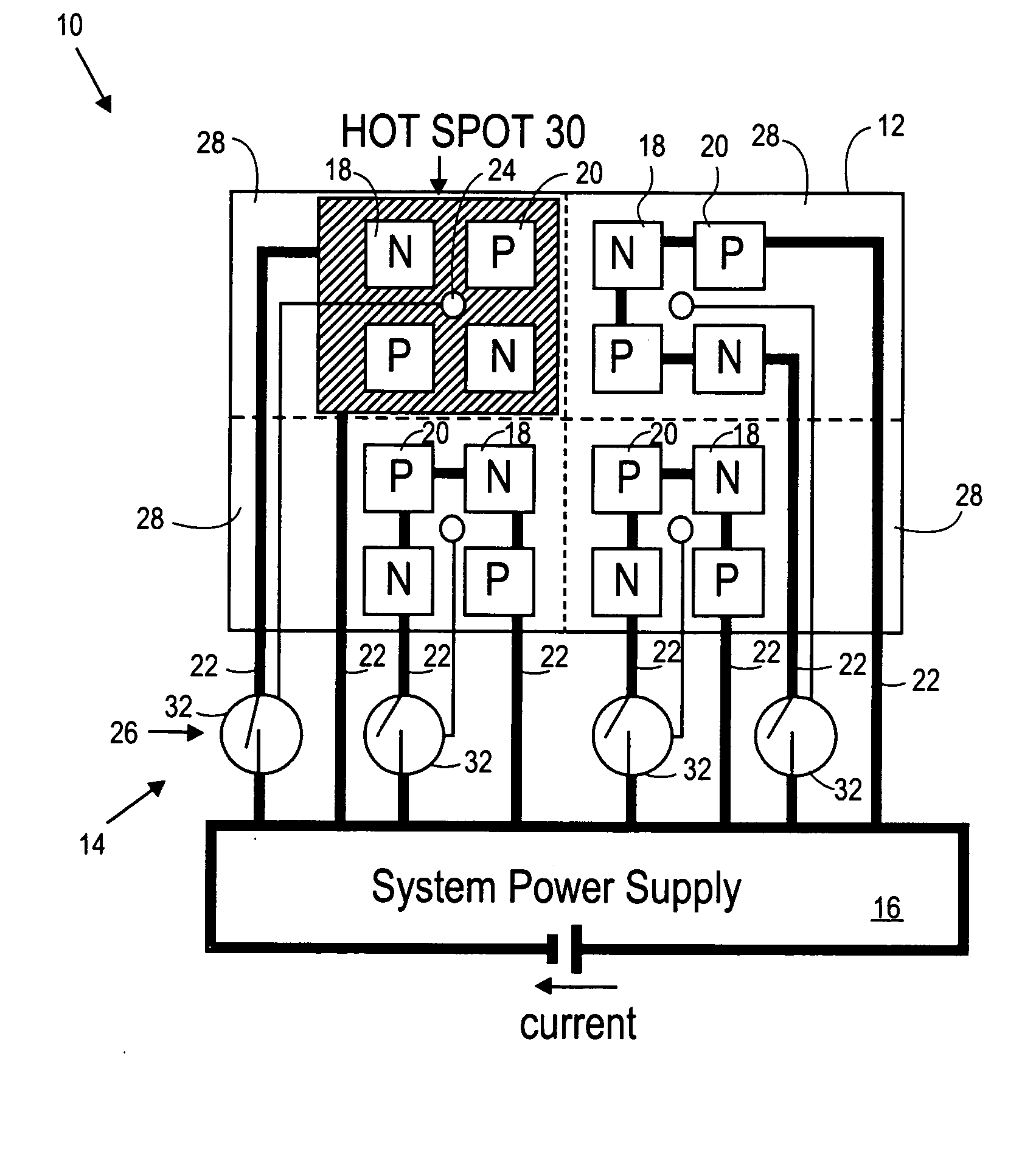
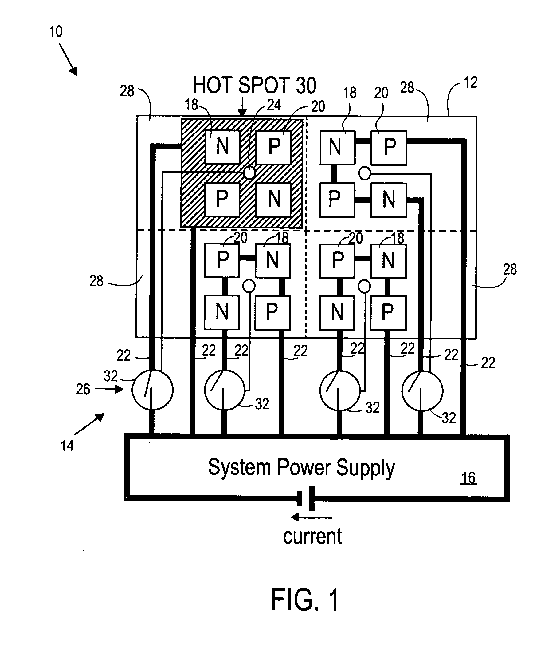
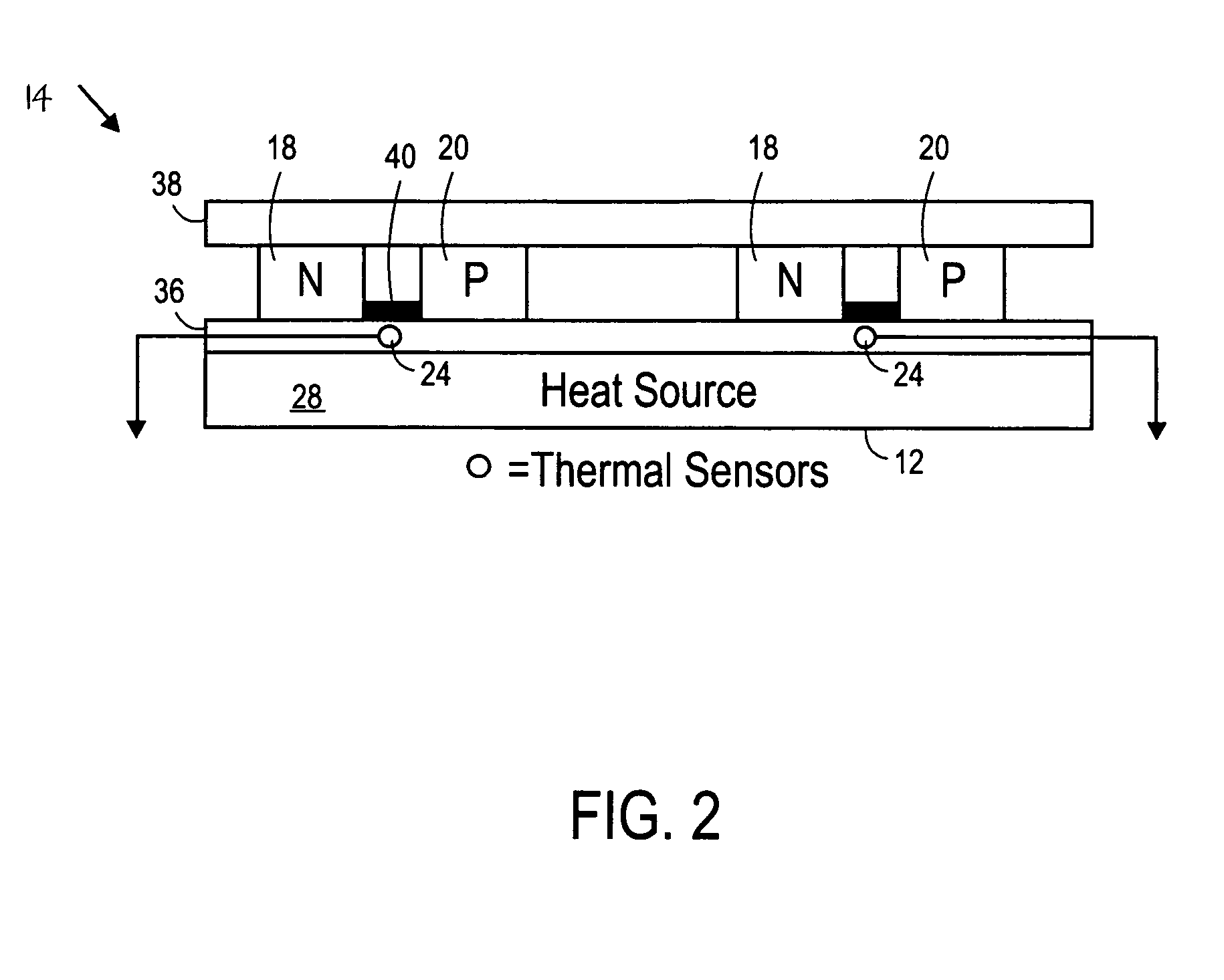
[0012]FIG. 1 of the accompanying drawings illustrates a computer subassembly 10, according to an embodiment of the invention, which includes an electronic component in the form of a processor 12 and a cooling system 14. The cooling system 14 includes a system power supply 16, a plurality of n-type thermoelectric elements 18, a plurality of p-type thermoelectric elements 20, a plurality of conductors 22, a plurality of temperature sensors 24, and a control apparatus 26.

[0013] The processor 12 can be divided into rows and columns with an array of areas 28 being defined where respective rows and columns intersect. The processor 12 has an integrated circuit formed which, when operated, generates heat. The heat generated by the processor 12 may be more in some of the areas 28 than in others and may vary over time. A hot spot 30 may be created where the temperature of the processor 12 is warmer in one of the areas 28 than in other ones of the areas 28.

[0014] A plurality of the thermoele...


PUM


Abstract

A cooling system for an electronic component is provided. The cooling system includes a plurality of thermoelectric elements for placement above a plurality of different areas of the electronic component. The cooling system has a plurality of conductors connected to the thermoelectric elements for providing current to the thermoelectric elements, such that the thermoelectric elements pump heat away from the respective areas. The cooling system has a control apparatus connected to the conductors for controlling current provided to the thermoelectric elements relative to one another based on heat generated at the different areas.

Description

BACKGROUND OF THE INVENTION [0001] 1). Field of the Invention [0002] This invention relates generally to a computer subassembly and more specifically to a cooling system for an electronic component of a computer subassembly. [0003] 2). Discussion of Related Art [0004] As semiconductor devices, such as processors, operate at continually higher data rates and higher frequencies, they generally consume greater current and produce more heat. [0005] Heat spreaders, heat sinks, and fans have traditionally been provided to processors of computers. These devices cool a processor over its entire area. A semiconductor device such as a processor does not generate heat uniformly so that hot spots are created in certain areas. Power provided to the processor has to be limited so that there are no hot spots with temperatures above a predetermined temperature. More power can be provided to the entire processor if the temperatures of the hot spots can be reduced. BRIEF DESCRIPTION OF THE DRAWINGS [...

Claims


Application Information

Patent Timeline
Patent Type & Authority Applications(United States)
IPC IPC(8): H01L23/34H01L23/38
CPCH01L23/34H01L23/38H01L2924/0002H01L2924/00G06F1/20
Inventor LEIJA, JAVIER M.LUCERO, CHRISTOPHER D.
Owner TAHOE RES LTD
Why Eureka
Try Eureka