Flanged vortex flowmeter with unitary tapered expanders

a flowmeter and expander technology, applied in the direction of volume/mass flow by dynamic fluid flow effect, measurement devices, instruments, etc., can solve the problem that the flowmeter cannot be relied on to provide an accurate indication of flow, and the flow velocity range is lower in the piping system

Active Publication Date: 2005-05-05
MICRO MOTION INC
View PDF6 Cites 61 Cited by
  • Summary
  • Abstract
  • Description
  • Claims
  • Application Information

AI Technical Summary

Benefits of technology

[0006] A manufacturing procedure of a vortex flowmeter is disclosed that allows for assembly of a vortex sensor assembly with one of two or more unitary flowtubes that have bores size numbers that are smaller than flowtube flange size numbers in two or more size number steps. The unitary flowtubes include flanges, flowtube bores and expanders that provide a smooth flow transition from the larger flanges to the smaller bores that is free of joints between the flowtube bore and the expanders.

Problems solved by technology

This desire to reduce power loss leads to use of larger pipe sizes and lower ranges of fluid flow velocity in the piping system.
When flow velocities are below a lower limit of measurable flow, the vortex flowmeter cannot be relied upon to provide an accurate indication of flow.

Method used


Image

  • Flanged vortex flowmeter with unitary tapered expanders
  • Flanged vortex flowmeter with unitary tapered expanders
  • Flanged vortex flowmeter with unitary tapered expanders

Examples


Embodiment Construction

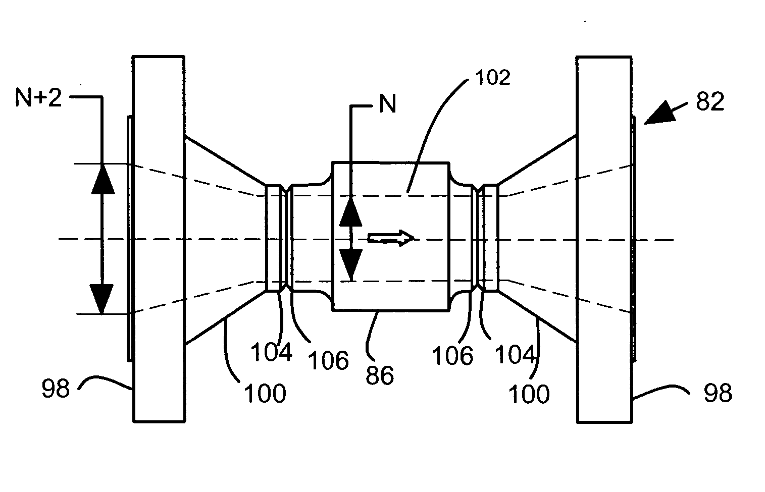
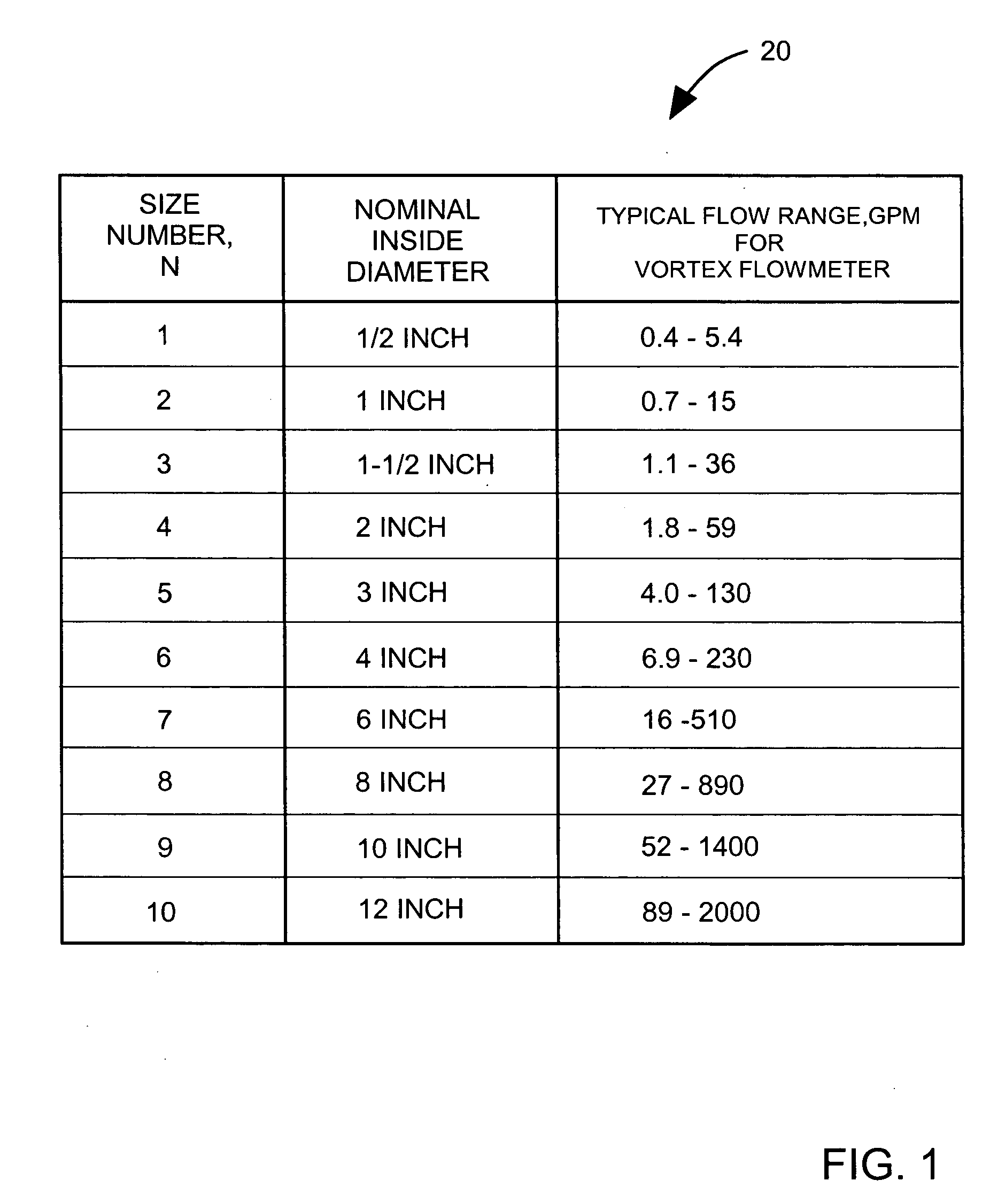
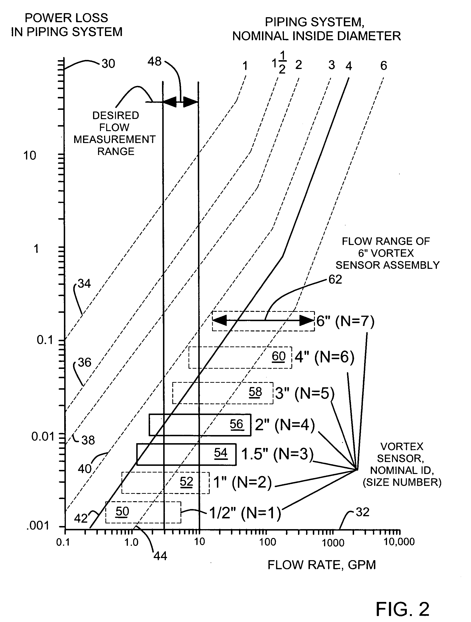
[0019] A manufacturing procedure for a vortex flowmeter is disclosed that allows for assembly of a vortex sensor assembly with one of two or more unitary flowtubes that have bores that are smaller than the flowtube flanges in two or more size number steps. The unitary flowtubes include flanges, flowtube bores and expanders (also called reducers) that provide a smooth flow transition from the larger flanges to the smaller bores. The methods disclosed allow for many combinations of bore size numbers and flange size numbers to be assembled to obtain a desired flow range while having only a single type of vortex sensor with a standard sensor interface in inventory.

[0020] The flow from a flanged piping system connected to the vortex flowmeter is increased in velocity as it passes through the smaller bore. This arrangement effectively shifts the fluid flow into the measurement range of the vortex flowmeter so that the flow can be measured accurately. In embodiments where the pipe diamete...


PUM


Abstract

A manufacturing procedure of a vortex flowmeter is disclosed that allows for assembly of a vortex sensor assembly with one of two or more unitary flowtubes that have bores that are smaller than the flowtube flanges in two or more size number steps. The unitary flowtubes include flanges, flowtube bores and expanders (also called reducers) that provide a smooth flow transition from the larger flanges to the smaller bores.

Description

FIELD OF THE INVENTION [0001] This invention relates to flanged vortex flow meters. In particular, this invention relates to connecting a vortex flowmeter to a flanged piping system that has a diameter that is larger than a diameter of the vortex flowmeter bore. BACKGROUND OF THE INVENTION [0002] Vortex flowmeters are used in the industrial process control field for measuring a flow rate of a fluid. Vortex flowmeters are typically inserted in a flow pipe or conduit that carries the fluid to be measured. Industry applications include petroleum, chemical, pulp and paper, mining and materials, oil and gas. The operating principal of a vortex flowmeter is based on a phenomenon of vortex shedding known as the von Karman effect. As fluid passes a bluff body, it separates and generates small eddies or vortices that are shed alternately along and behind each side of the bluff body. These vortices cause areas of fluctuating pressure that are detected by a sensor. While the frequency of vorte...

Claims


Application Information

Patent Timeline
Patent Type & Authority Applications(United States)
IPC IPC(8): G01F1/32
CPCG01F1/3209
Inventor BENGTSON, DARROLL D.
Owner MICRO MOTION INC
Why Eureka
Try Eureka