Support post with locking feature

a technology of support post and locking feature, which is applied in the direction of transportation and packaging, tray containers, packaging goods types, etc., can solve the problems of not being able to view without and achieving stacking strength

Active Publication Date: 2005-05-05
SONOCO DEV INC
View PDF21 Cites 28 Cited by
  • Summary
  • Abstract
  • Description
  • Claims
  • Application Information

AI Technical Summary

Benefits of technology

[0013] In a key feature of the invention, the two locking tabs are oriented on non-parallel planes so as to prevent the post from moving in any lateral direction during use. The locking tabs are spaced inwardly from the outer perimeter of the base so that portions of the base abut each outer wall member to help hold the posts in place.
[0014] In a second embodiment, each of the paper corner posts has a polygonal locking portion disposed at the bottom end for interlocking with the molded EPS base. The polygonal locking portion preferably is a hollow tubular subsection of the post. For added stability, the corner posts may also have a substantially planar locking tab located at one outer end.

Problems solved by technology

The result is a packaged appliance that is protected from impacts, but cannot be viewed without removing the corrugated box.
A disadvantage of EPS packages is that stacking strength is achieved by stacking through the appliance since the EPS corner protectors provide minimal, if any, stacking strength.

Method used


Image

  • Support post with locking feature
  • Support post with locking feature
  • Support post with locking feature

Examples


Embodiment Construction

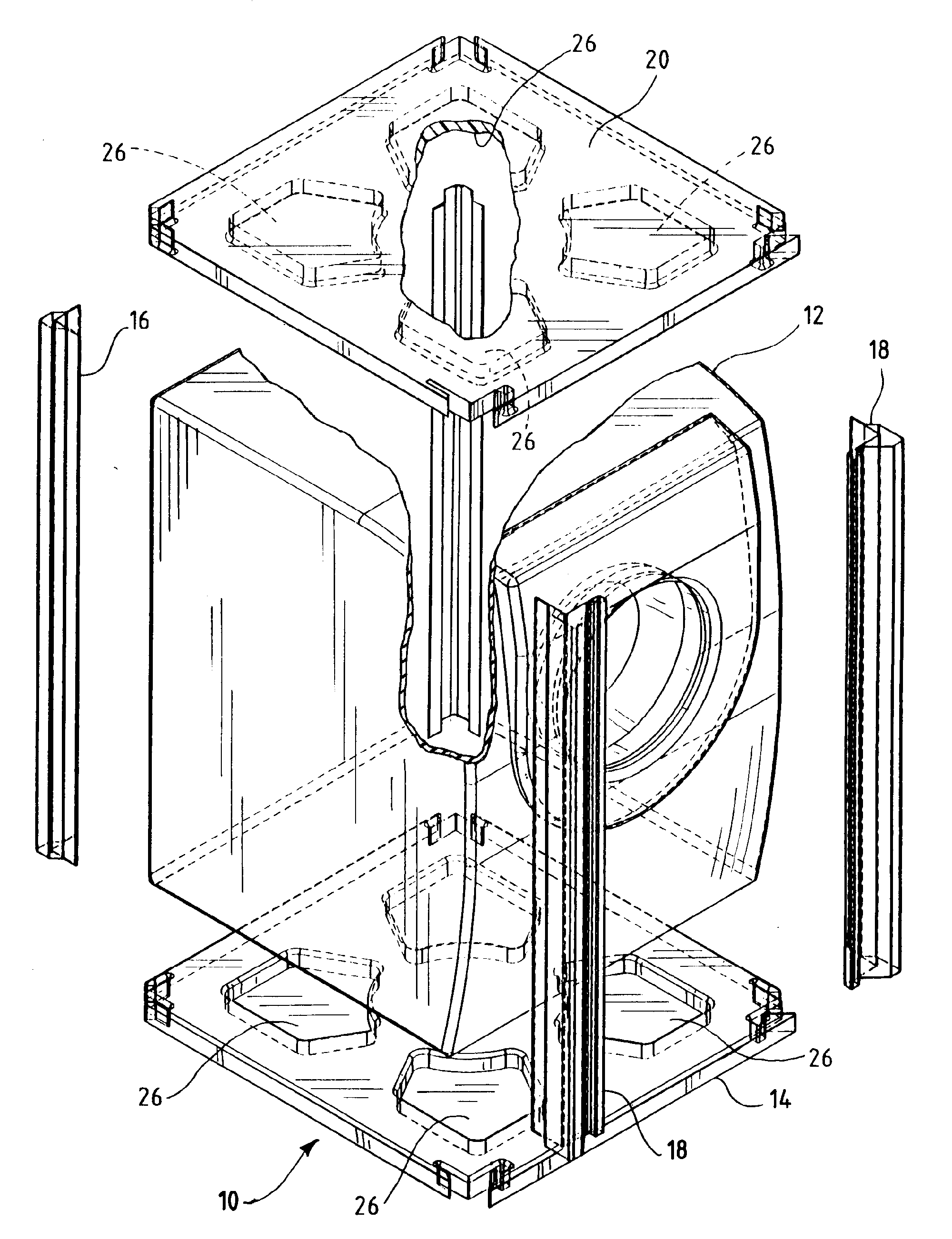
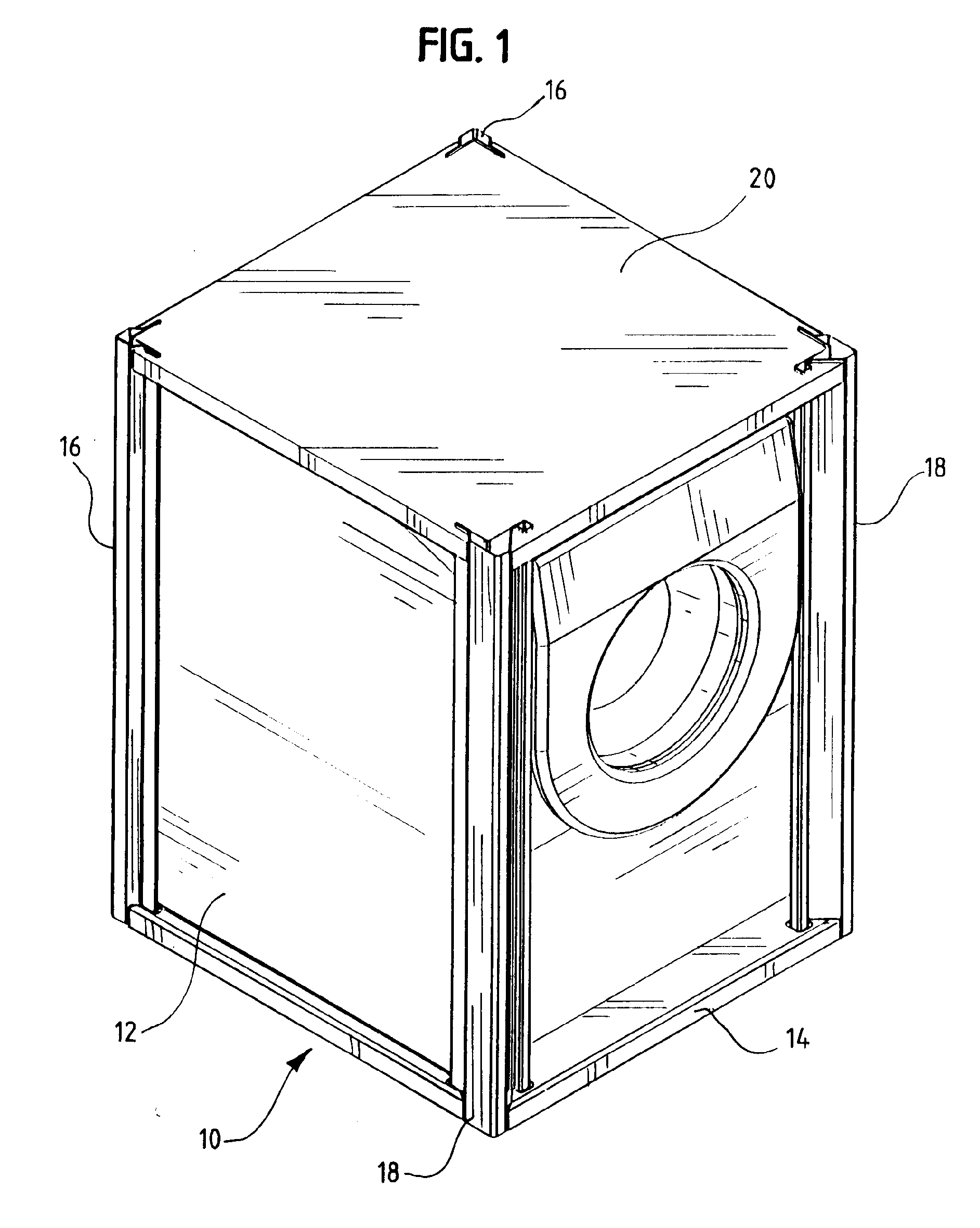
[0021] Turning to the drawings, there is shown in FIGS. 1 and 2 a preferred embodiment of the present invention, a packaging assembly 10 for protecting and cushioning a product such as a large appliance 12. The packaging assembly 10 comprises a base 14, two rear corner posts 16 and two front corner posts 18 affixed to the base 14, and a top cap 20. Optional transparent film (not shown) may be wrapped around the package 10 or draped over the product 12 to protect the product 12 from dust and dirt.

[0022] As best shown in FIG. 3, the base 14 is substantially rectangular and symmetrical about a front to rear central axis. The base 14 has portions for supporting the product and may have additional openings (not shown) for accommodating product feet. Openings 22, 24 at the rear and front corners have the same shape at the cross-sectional shape of the bottom ends of the rear and front corner posts 16, 18 in order to receive the corner posts 16, 18 in interlocking fashion. Preferably the b...


PUM


Abstract

An improved open-sided package assembly for protecting and cushioning a product such as a large appliance, the assembly comprising a molded EPS base and top cap and four paper corner posts extending from the base to the top cap. The corner posts are shaped in such a way that when they are inserted into the base or top cap they do not fall out.

Description

BACKGROUND OF INVENTION [0001] This patent relates to protective packaging for large products such as household appliances. More particularly, this patent relates to a packaging system that includes laminated paper support posts that interlock with an EPS base or top cap. [0002] The usual practice in the appliance manufacturing industry has been to fasten the bottom of the appliance to a wooden pallet or other type of base during manufacture. The base is dimensioned to be oversized relative to the appliance's width and depth so that the perimeter of the base extends beyond the appliance perimeter. After the appliance has been completely assembled (and while it is mounted on the base) a rigid but collapsible four-sided corrugated box or sleeve having open top and bottom ends is placed over the appliance and secured to the base. Before a top cap is placed over the box, support posts (a.k.a. corner posts) are inserted at each corner of the appliance between the appliance and the corrug...

Claims


Application Information

Patent Timeline
Patent Type & Authority Applications(United States)
IPC IPC(8): B65D61/00
CPCB65D2585/6855B65D61/00
Inventor BAECHLE, JAMES
Owner SONOCO DEV INC
Why Eureka
Try Eureka