Closeable self-venting spout

a self-venting, pouring spout technology, applied in the direction of liquid transferring devices, liquid handling, packaging goods types, etc., can solve the problems of not only waste of spilled materials, material being transferred may splash or flow over the outer portions of the container, and the size of the opening in the filling container may not be compatible with the size of the opening, so as to reduce the volume of material, increase the dimension of the airflow passageway, and smooth the flow of air

Inactive Publication Date: 2005-05-05
NITEC NIELSEN IDAHO TOOL & ENG
View PDF27 Cites 11 Cited by
  • Summary
  • Abstract
  • Description
  • Claims
  • Application Information

AI Technical Summary

Benefits of technology

[0024] The smoothness of the flow of air into the filling container and the flow of liquid out of the container is further enhanced by sequentially reducing the dimensions of the fluid flow passageway, as the passageway extends away from the filling container. While also increasing the dimensions of the airflow passageway as the airflow passageway ends away from the filling container. This configuration ensures that an air bubble will exist at a location in the vent tube that is higher than liquid that is positioned in the full diameter of the fluid in the liquid flow chamber. In the present invention, the fluid flow passageway is configured so as to have a larger first portion positioned closest to the first end of the spout and to decrease in size so as to define a passageway having a smaller diameter and therefore able to hold a lesser volume of material thereafter. This volumetric change concentrates the gravitational pressure upon the fluid column at the joint or elbow of the device and allows the internal air bubble to rise above the fluid level. This variation in size slows the rate at which liquid will exit the device and allows the rate at which air enters the filling device to be greater than the rate at which liquid leaves this same container. As a result, sufficient air to replace exiting liquid is always present and the problems of chugging and surging, which exist in the prior art, are done away with.
[0025] The configuration of the sliding sleeve allows for the air flow and the liquid flow chambers to be effectively telescoped in length, as the device is moved between an open and a closed position. Thus, allowing the venting system and the liquid flow chambers to be maintained separately and preventing the problems of vacuum formation, surging, and chugging which are found in the prior art. The sliding sleeve works with portions of the end nozzle in a sliding type configuration which allows the apertures to be alternatively opened and closed, while still allowing the flow of air and the flow of liquid out of the device to be alternatively stopped or started.
[0026] When the sliding sleeve is brought into compression against the sides of the end nozzle, and the stopper is placed in a designated location against an inner portion of the sliding sleeve, the flow of liquid material out of the device is stopped. However, when the engagement between the sliding sleeve and the side of the end nozzle is relaxed, the flow of material through the device occurs. When the sliding sleeve is opened, a venturi effect caused by the passing flow of liquid and air is created and on the exiting fluid flow is created and the air and fluid are prevented from mixing. The combination of these features delivers unimpeded air to the vent tube near the filling container neck and does away with the gurgling, surging and splashing that are found in the prior art.
[0027] When the spout is first placed upon the device and the container is inverted. Liquid will fill both the airflow and liquid flow passageways. However, when the device is opened, the venturi effect, which is brought about by the variations in the dimensions of the spout, causes the liquid that is within the air flow passageway to rapidly evacuated from the air flow passageway and to be rapidly replaced with air. Once the flow of air through the airflow passageway has been established, the physical structure of the spout maintains the separation between the flow of air and liquid in opposite directions through the spout.
[0028] The present invention also provides a significant advantage in that it eliminates the use of O-rings to seal the device, thus reducing manufacturing costs, and the number of device failures. The shape of the various pieces within the device are self nesting and self sealing thus allowing the parties involved in the manufacture of such devices to reduce manufacturing costs. This venting system is fully internally self-contained. Any erratic fluid behaviors can be controlled internally and does not expose consumers or equipment to wayward sprays or gurgles.

Problems solved by technology

In the process of pouring this material from one container into another, a variety of problems arise.
One problem is that the size of the opening in the filling container may not be compatible with the size of the opening on the receiving container.
As a result, the material being transferred may splash or flow over the outer portions of the container being filled.
When this occurs, the spilled material is not only wasted but a variety of damaging effects to persons and things in the surrounding area can also occur.
Spilled gasoline emits fumes, which can be hazardous both from their inhalation as well as for the increased risk of flammability.
Furthermore, the substances themselves may have a variety of damaging effects upon the surrounding environment.
However, these nozzles and spouts bring with them a variety of problems as well.
One of the problems with many of these types of nozzles is their inability to allow for a smooth transfer of air into the container to replace the liquid that is leaving the container.
These surges can result in spills and overflow of material out of the device.
The repetitive surging of air into the device and the surging exit of liquid out of the device can also cause a chugging or gurgling sound to occur.
This chugging or gurgling makes filling a container to a desired level without spilling difficult because the quantity of material that will surge forward is unpredictable.
This uneven flow can further contribute to spillage and / or over filling of the container.
Another problem with the prior art nozzles is that when utilizing such a nozzle, it is difficult to determine when the receiving container is full.
As a result, an individual may continue to pour liquid into this container and cause the contents to overflow.
Another problem that exists in the prior art is that access to these containers may be obtained by individuals such as small children, who may inhale the fumes or ingest the gasoline and suffer significant damaging effects.
Another problem that exists in the prior art is the necessity of O-rings as sealing devices.
As a result, O-rings place substantial static pressures upon the materials that make up the various spout pieces and can result in failure of the materials from which the spout is made.
Additionally, over time the O-rings themselves may also wear out and be degraded by the chemicals that they are trying to seal.
Another problem with such devices is that they can be prohibitively expensive to manufacture and produce.

Method used


Image

  • Closeable self-venting spout
  • Closeable self-venting spout
  • Closeable self-venting spout

Examples


Embodiment Construction

[0048] While the invention is susceptible of various modifications and alternative constructions, certain illustrated embodiments thereof have been shown in the drawings and will be described below in detail. It should be understood, however, that there is no intention to limit the invention to the specific form disclosed, but, on the contrary, the invention is to cover all modifications, alternative constructions, and equivalents falling within the spirit and scope of the invention as defined in the claims.

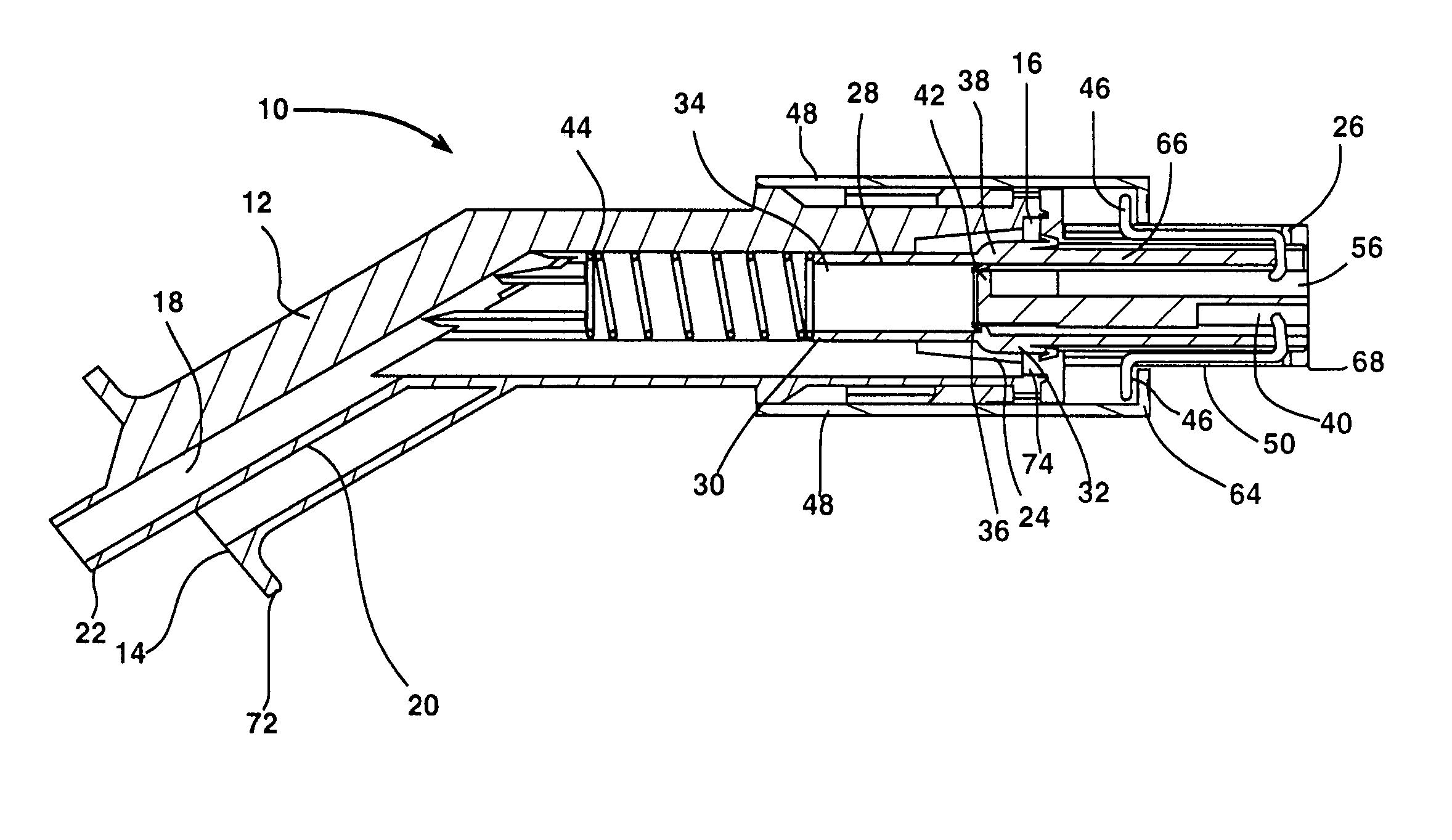
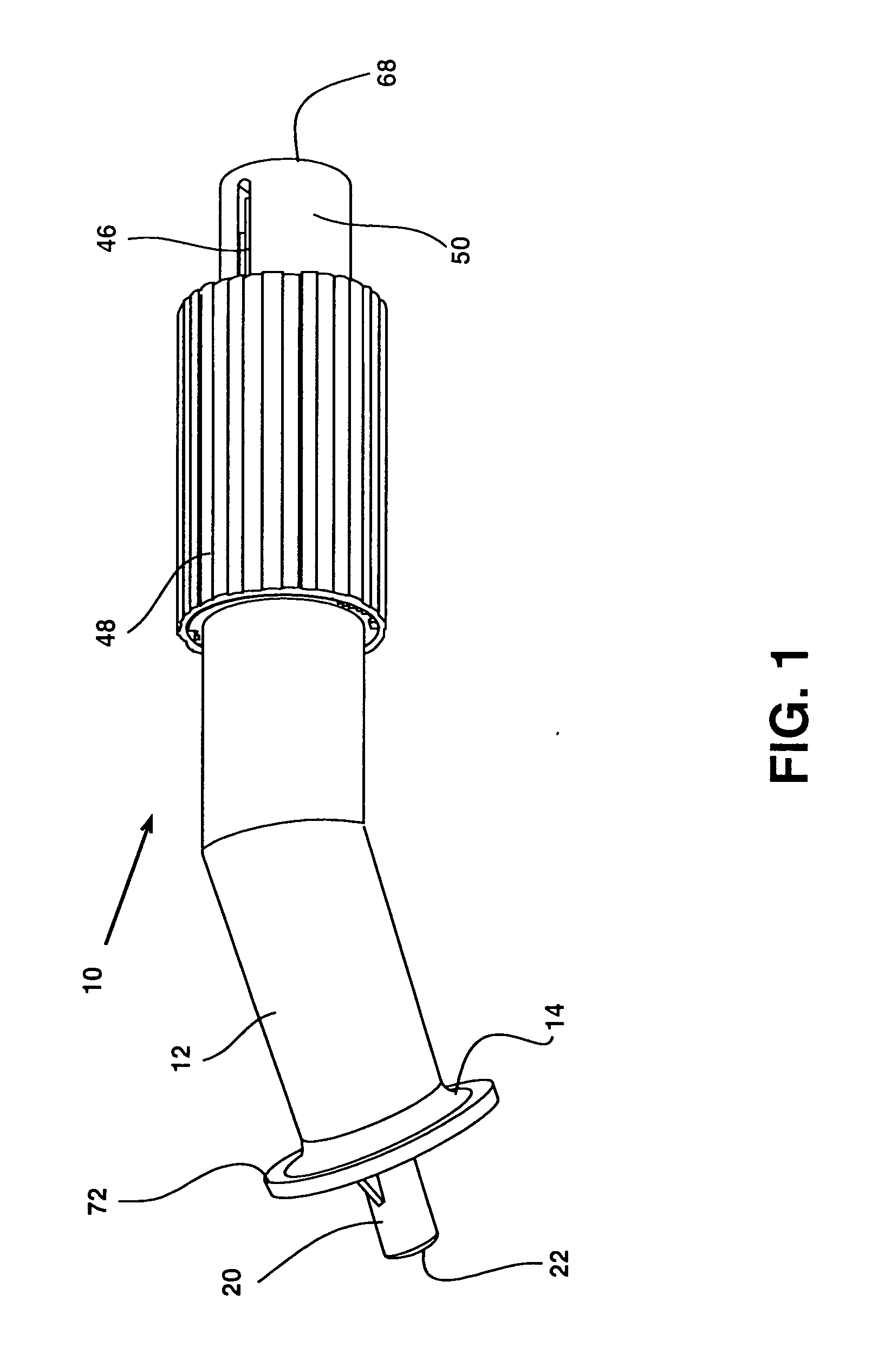
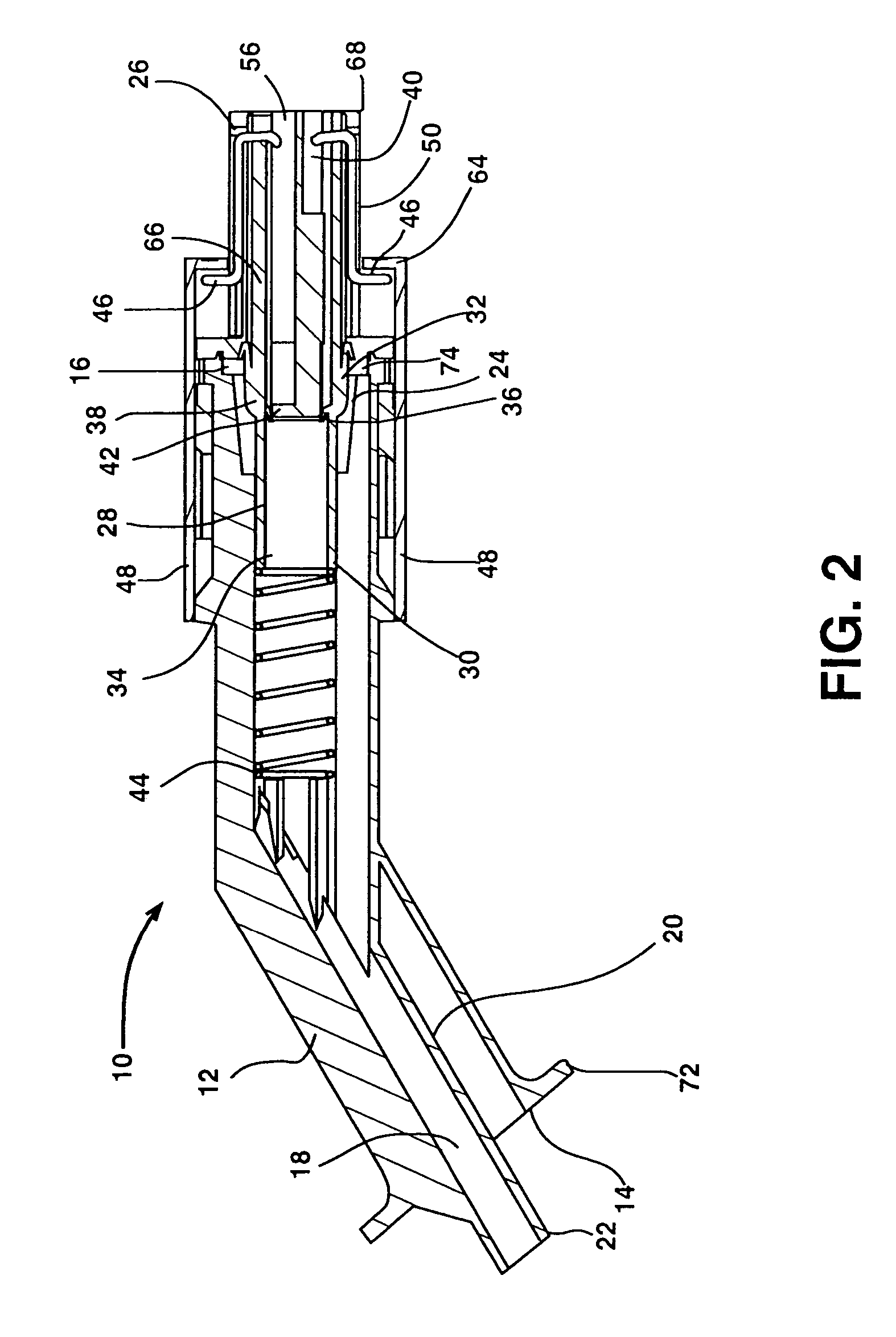
[0049]FIG. 1 shows a side view of the present invention. The present invention is a spout 10 comprised of a spout body 12 having a first end 14 extending along a length to a second end 16 (shown in FIGS. 2, 3 and 4). The first and second ends 14, 16 of the spout body are open and define a spout body passageway 18 (shown in FIG. 2, 3, 4) which extends from the first end 14 to the second end 16. In this preferred embodiment, the angle between the first and second ends 14, 16 is co...


PUM

PropertyMeasurementUnit
angleaaaaaaaaaa
oblique angleaaaaaaaaaa
lengthaaaaaaaaaa

Abstract

A non-spilling detachable pouring spout configured to transfer liquid from a non-vented filling container to a receiving container. This spout having a spout body defining an open passageway extending from an open first end to an open second end this open passageway having a generally tubular shaped hollow inner conduit positioned within the first hollow passageway, and defining a second hollow passageway. An intermediate sleeve is configured for attachment to the device and is further configured to seal against portions of the spout body and the inner conduit so as to variously control the flow of materials out of the spout body. The movement of said sleeve is controlled by movement of a child resistant sheath.

Description

BACKGROUND OF THE INVENTION [0001] 1. Field of the Invention [0002] The present invention generally relates to detachable pouring spouts that are configured to transfer the contents of a filling container to a receiving container. More particularly, the present invention relates to a detachable self-venting, non-spilling pouring spout, which can be selectively opened and closed when attached to a filling container. In the preferred embodiment, the present invention is a selectively openable self-venting child-resistant spout that allows for smooth transfer of liquid materials from a non-vented holding container to a receiving container. [0003] 2. Background Information [0004] Many products are stored in one container, but must be transferred to another container for use. An example of such a product is gasoline, which may be stored in a variety of differently configured containers, but which in order to be used must be transferred to a refillable holding tank that is connected to an...

Claims


Application Information

Patent Timeline
Patent Type & Authority Applications(United States)
IPC IPC(8): B67D7/00
CPCB67D7/005
Inventor NIELSEN, ROGER B.
Owner NITEC NIELSEN IDAHO TOOL & ENG
Why Eureka
Try Eureka