Inductively coupled ballast circuit

a ballast circuit and inductive coupling technology, applied in the field of ballasts, can solve the problems of complex replacement, large number of direct electrical connections, and difficulty in installing and removing load from ballast, and achieve the effect of small change regions

Inactive Publication Date: 2005-05-05
PHILIPS IP VENTURES BV
View PDF99 Cites 351 Cited by
  • Summary
  • Abstract
  • Description
  • Claims
  • Application Information

AI Technical Summary

Benefits of technology

[0007] Conventional ballast control circuits employ bipolar transistors and saturating transformers to provide power. The ballast control circuits oscillate at frequencies related to the magnetic properties of the materials and winding arrangements of these transformers. Circuits with saturating transformer oscillators produce an output in the category of a square wave, require the transistors of the half bridge to hard-switch under load and require a separate inductor to limit the current through the load. Conventional circuits chop the available power supply voltage, developing voltage spikes at the corners of the square wave as a consequence of the current limiting inductor. Inductive couplings rely on electromagnetic induction to transfer power from a primary coil to a secondary coil. The amount of current induced in the secondary coil is a function of the changes in the magnetic field generated by the primary coil. Accordingly, the amount of current transferred through an inductive coupling is dependent, in part, on the waveform of the current driving the primary. A square waveform has relatively small regions of change and therefore provides relatively inefficient transfer of power.

Problems solved by technology

Direct electrical connections present a number of problems.
First, direct electrical connections make it difficult to install and remove the load from the ballast.
If the ballast or the load is damaged, replacement is complicated by the permanent connections.
Removable connectors are also subject to corrosion and may be inadvertently or unintentionally disconnected, for example, by vibrations.
For example, in wet environments, exposed electrical connections are subject to a short circuit.
Third, direct electrical connections provide a direct and essentially unimpeded path for electricity to flow between the ballast and the load.
As a result, power surges and other potentially damaging abnormalities in one element can be directly transfer to the other, thereby permitting problems in one component to damage or even destroy the other.
First, inductive couplings do not include permanent or removable physical connectors.
Unfortunately, conventional inductively coupled ballasts suffer from a number of problems associated primarily with efficiency.
A square waveform has relatively small regions of change and therefore provides relatively inefficient transfer of power.

Method used


Image

  • Inductively coupled ballast circuit
  • Inductively coupled ballast circuit
  • Inductively coupled ballast circuit

Examples


Embodiment Construction

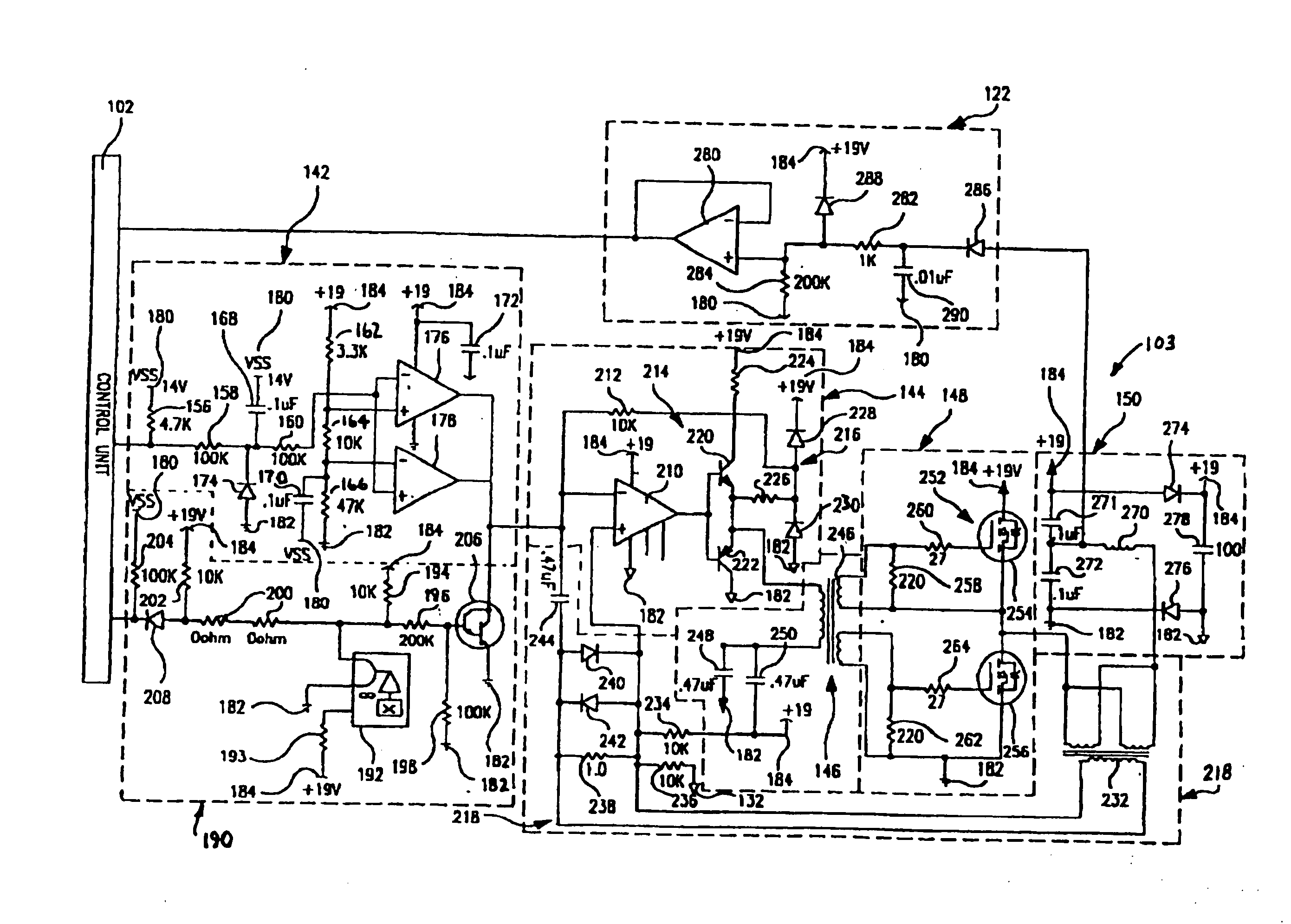
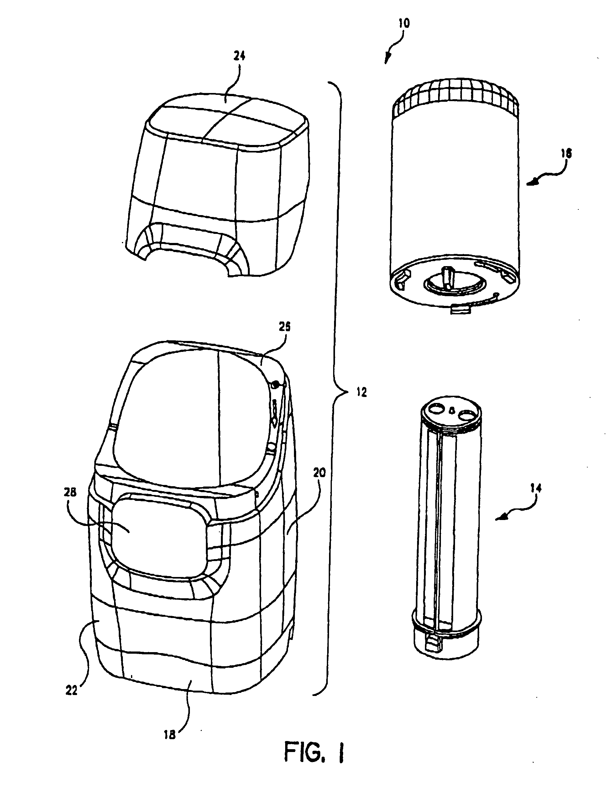
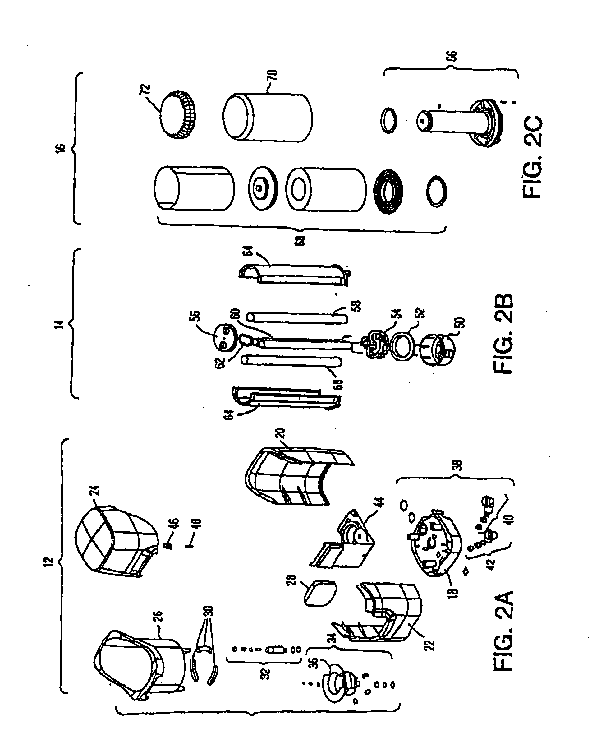
[0037] The present invention is directed to an inductively coupled ballast circuit that is capable of providing power to a wide variety of electrically powered components in numerous applications. For purposes of disclosure, embodiments of the ballast circuit will be described in connection with a water treatment system, and more specifically in connection with the powering of an ultraviolet lamp in a water treatment system. Although described in connection with this particular application, the present invention is well-suited for use in providing power to other types of lamps, such as incandescent, fluorescent and halogen lamps used in numerous lighting applications, such as indoor and outdoor light fixtures, desk lamps, outdoor signage, decorative lighting, automotive lighting, underwater lighting, intrinsically safe lighting, and landscape lighting, to name only a few lighting configurations and applications. The present invention is also well suited for providing power to non-li...


PUM

PropertyMeasurementUnit
resonant frequencyaaaaaaaaaa
diameteraaaaaaaaaa
diameteraaaaaaaaaa

Abstract

A ballast circuit is disclosed for inductively providing power to a load. The ballast circuit includes an oscillator, a driver, a switching circuit, a resonant tank circuit and a current sensing circuit. The current sensing circuit provides a current feedback signal to the oscillator that is representative of the current in the resonant tank circuit. The current feedback signal drives the frequency of the ballast circuit causing the ballast circuit to seek resonance. The ballast circuit preferably includes a current limit circuit that is inductively coupled to the resonant tank circuit. The current limit circuit disables the ballast circuit when the current in the ballast circuit exceeds a predetermined threshold or falls outside a predetermined range.

Description

[0001] This application is a continuation of U.S. patent application Ser. No. 10 / 246,155 entitled “Inductively Coupled Ballast Circuit,” filed Sep. 18, 2002; which is a continuation-in-part of U.S. patent application Ser. No. 10 / 175,095 entitled “Fluid Treatment System,” filed Jun. 18, 2002, now U.S. Pat. No. 6,673,250; which is a continuation-in-part of U.S. patent application Ser. No. 09 / 592,194 entitled “Fluid Treatment System,” filed Jun. 12, 2000, now U.S. Pat. No. 6,436,299. U.S. patent application Ser. No. 09 / 592,194 (now U.S. Pat. No. 6,436,299) claims the benefit under 35 U.S.C. §119(e) of U.S. Provisional Patent Application Ser. No. 60 / 140,159 entitled “Water Treatment System with an Inductively Coupled Ballast,” filed Jun. 21, 1999 and U.S. Provisional Patent Application Ser. No. 60 / 140,090 entitled “Point-of-Use Water Treatment System,” filed Jun. 21, 1999. [0002] This application hereby incorporates by reference U.S. patent application Ser. No. 09 / 596,416 entitled “Poin...

Claims


Application Information

Patent Timeline
Patent Type & Authority Applications(United States)
IPC IPC(8): A61L2/10C02F1/00C02F1/32C02F9/00H05B37/03H05B41/36
CPCA61L2/10Y02B20/19C02F1/008C02F1/325C02F9/005C02F2201/3222C02F2201/3228C02F2201/326C02F2209/005C02F2209/008C02F2209/40H05B37/03H05B41/24H05B41/36C02F1/001Y02B20/00H05B47/25C02F9/20
Inventor KUENNEN, ROY W.BAARMAN, DAVID W.MOLLEMA, SCOTT A.MARKHAM, RONALD C.DENEN, DENNIS J.
Owner PHILIPS IP VENTURES BV
Why Eureka
Try Eureka