Supercharge Your Innovation With Domain-Expert AI Agents!

Method and apparatus for measuring the effect of different lighting conditions

a technology for lighting conditions and methods, applied in the field of methods and apparatus for testing and assessment of eyesight defects and medical conditions, can solve the problems of no method or apparatus for measuring the effect of changes in lighting conditions

Inactive Publication Date: 2005-05-05
DIVERSE TECH & SYST
View PDF3 Cites 4 Cited by
  • Summary
  • Abstract
  • Description
  • Claims
  • Application Information

AI Technical Summary

Benefits of technology

[0018] For example, for those who suffer from migraine as a result of flicker, one can simulate different types of CRT, operating at different frequencies, and from this predict which screens are most likely to trigger the problem. One thus has a means of non-invasive therapy by creating a job environment which is the least harmful to any particular individual.

Problems solved by technology

Although various methods of testing such conditions are known, there is currently no method of or apparatus for measuring the effect of changes in lighting conditions.

Method used


Image

  • Method and apparatus for measuring the effect of different lighting conditions
  • Method and apparatus for measuring the effect of different lighting conditions
  • Method and apparatus for measuring the effect of different lighting conditions

Examples


Embodiment Construction

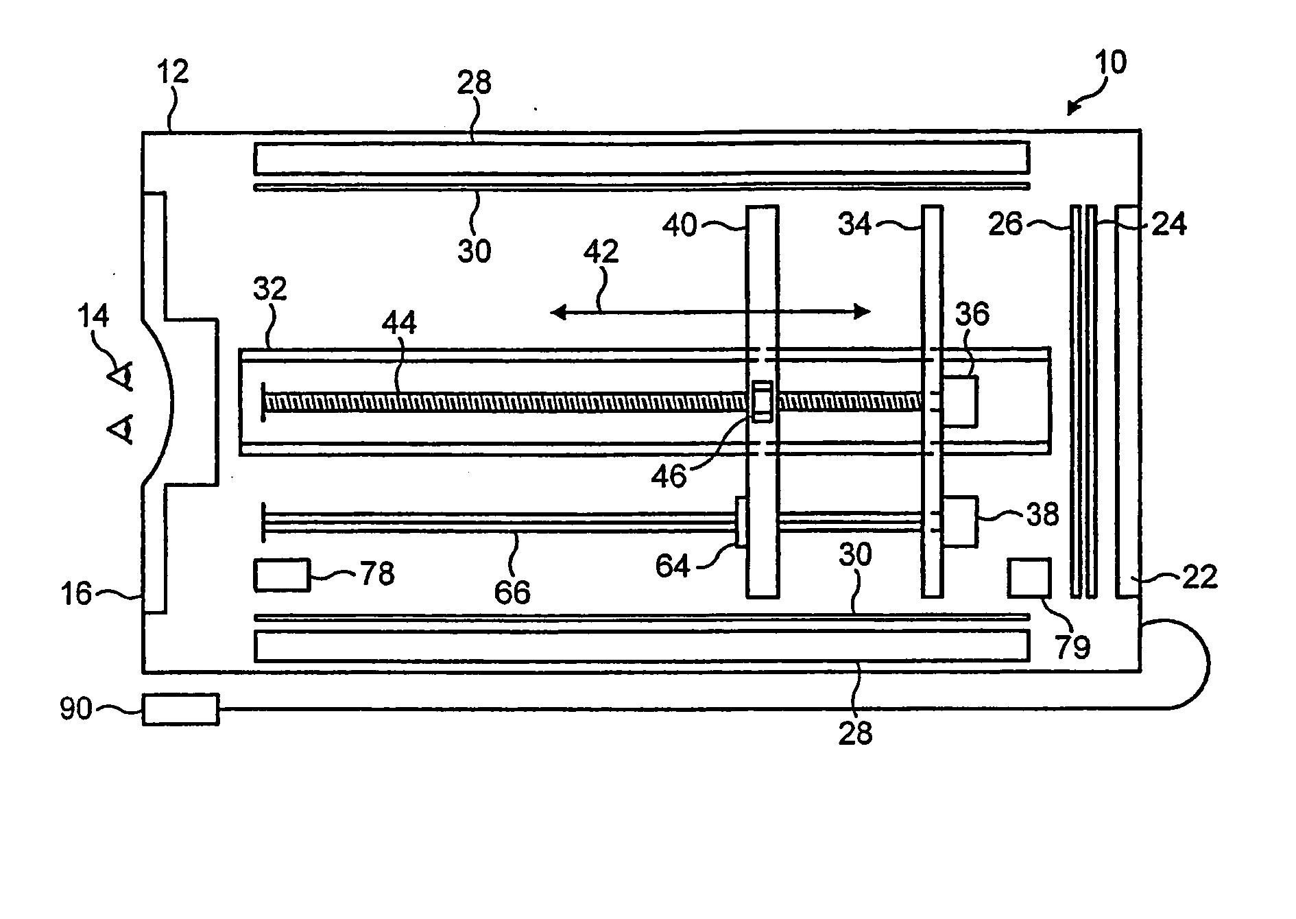
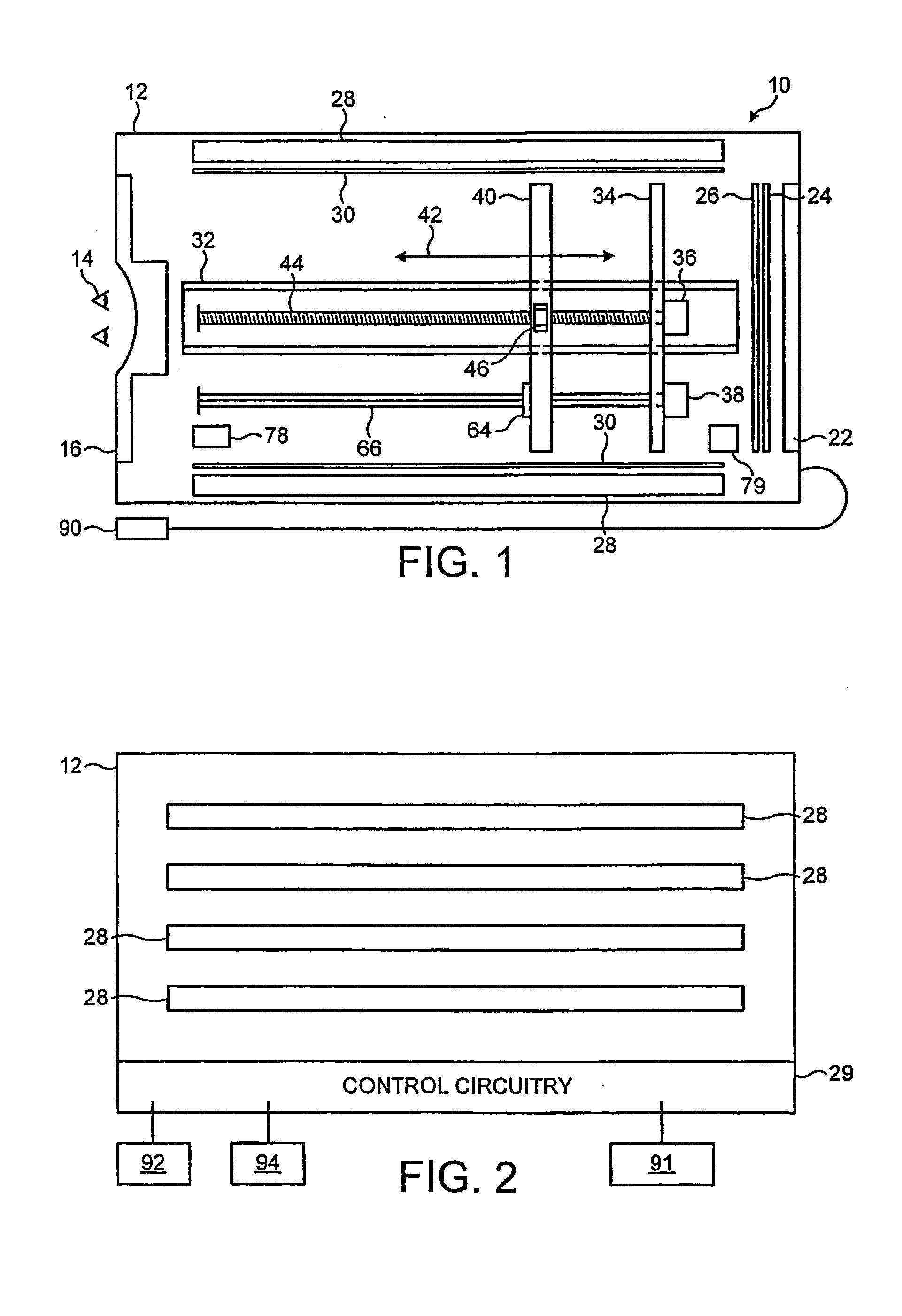
[0028] The optical assessment apparatus of the present invention is essentially a light box, and will hereinafter be referred to as such. In the drawings the light box is indicated generally at 10. It comprises a housing 12 from which extraneous light is excluded. An observer, represented by eyes 14, is positioned at the front end of the light box and views the interior of the light box through an aperture or apertures in the front end wall 16 of the housing. The aperture or apertures can be in the form of a slot or slots.

[0029] As shown in FIG. 7, a holder 18 can be mounted within the light box adjacent to the viewing slots, to receive lenses or filters 20. These are positioned in alignment with the eye slots. Preferably, the holder 18 has provision for the receipt of two lenses or filters in a side-by-side arrangement. Alternatively, the holder 18 could be in the form of a rotatable carousel, so that different lenses or filters can be brought selectively into alignment with the e...


PUM


Abstract

A light box (10) with a viewing aperture contains sources of illumination (22, 28) which can be adjusted and set to simulate different lighting situations and conditions. An observable image on a trolley (40) is movable towards and away from the observer (14) and also transversely to the line of sight of the observer. Movement is effected by stepping motors (36 and 38). Measurements are made of the response of the observer to movement of the image consequent on changes in the parameters affecting the observer's perception of the image. A comparative assessment can thus be made of the effect of changing the illumination.

Description

CROSS REFERENCE OF THE RELATED APPLICATION [0001] This application is a Continuation-In-Part of copending PCT application Ser. No. 10 / 464,491 filed on Jun. 19, 2003, the entire contents of which are hereby incorporated by reference and for which priority is claimed under 35 U.S.C. § 120. In addition, Applicant claims that this Continuation-In-Part Application also claims priority of Application No. PCT / GB03 / 01362 filed on Mar. 28, 2003 under 35 U.S.C. § 120, the entire contents of which are hereby incorporated by reference.FIELD OF THE INVENTION [0002] This invention relates to methods of and apparatus for the testing and assessment of eyesight defects and medical conditions associated with eyesight. It is more particularly concerned with methods of and apparatus for measuring changes in the human response to changes in lighting and / or the movement of images. [0003] Various medical conditions such as dyslexia, nystagmus, squint and migraine are affected by light conditions, i.e. by ...

Claims


Application Information

Patent Timeline
Patent Type & Authority Applications(United States)
IPC IPC(8): A61B3/06A61B5/00A61B5/16A61N5/06
CPCA61B3/06A61B3/066A61B5/161A61N2005/0663A61N5/0618A61N2005/0652A61B5/4863
Inventor JORDAN, IAN
Owner DIVERSE TECH & SYST
Features
  • R&D
  • Intellectual Property
  • Life Sciences
  • Materials
  • Tech Scout
  • Unparalleled Data Quality
  • Higher Quality Content
  • 60% Fewer Hallucinations
Learn More