
Method for rerouting MPLS traffic in ring networks

a technology of ring network and rerouting, applied in the field of communication, can solve the problems of traffic delay, bandwidth bottleneck, ineffective protection of sonet/sdh ring, etc., and achieve the effect of fast rerouting of traffi

Active Publication Date: 2005-05-05
ECE TELECOM LTD
View PDF10 Cites 31 Cited by
  • Summary
  • Abstract
  • Description
  • Claims
  • Application Information

AI Technical Summary

Benefits of technology

[0010] It is therefore an object of the present invention to provide a method for protecting MPLS traffic in networks comprising ring-like portions and enabling fast rerouting of the traffic in case of one or more failures in the network.
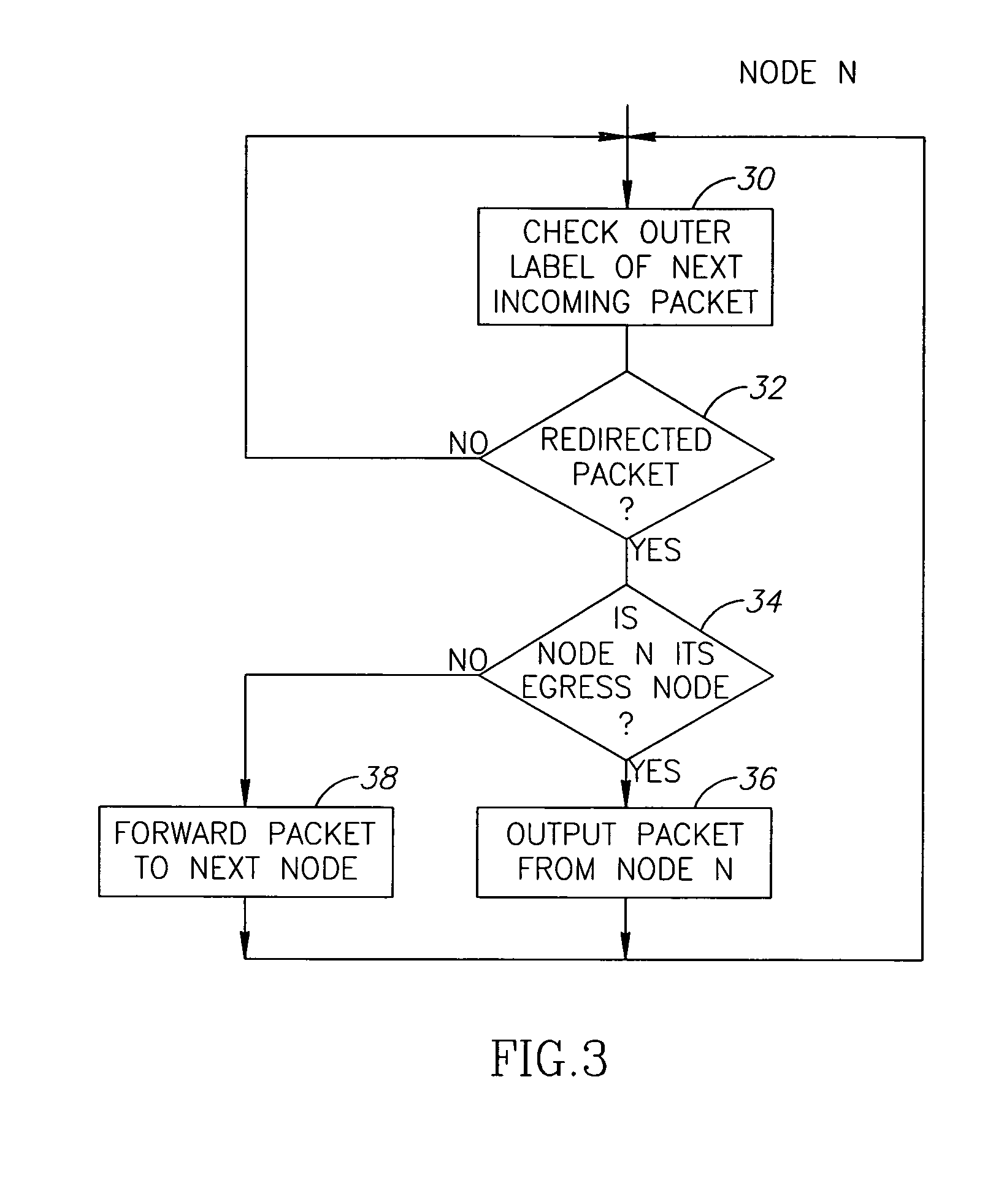
[0022] Owing to the fact that the method allows outputting the rerouted traffic from the protection path at egress node(s) of corresponding LSPs (contrary to the conventional concept of traffic protection in ring networks where the rerouted traffic can only be output from the main path at the egress node, after completing the whole way along the protection path and coming back to the main path at the node adjacent to the faulty section), the rerouted traffic will travel shorter distances in the network.
[0036] The above-described method is therefore applicable for a multi-ring network, and acquires an increased effect of fast rerouting.

Problems solved by technology

Yet, SONET / SDH ring protection is inefficient compared to packet-based protection and often creates bandwidth bottlenecks at a metro level.
As a result, the solution suffers from a traffic delay, is critical to multiple faults in the ring and is inefficient from the point of bandwidth reserved for ensuring protection in the excessive portions of the ring.
The method suffers from the drawbacks mentioned before, since it enforces the backup path to return the traffic into the ingress point of the ring where the LSP has started.

Method used


Image

  • Method for rerouting MPLS traffic in ring networks
  • Method for rerouting MPLS traffic in ring networks
  • Method for rerouting MPLS traffic in ring networks

Examples


Embodiment Construction

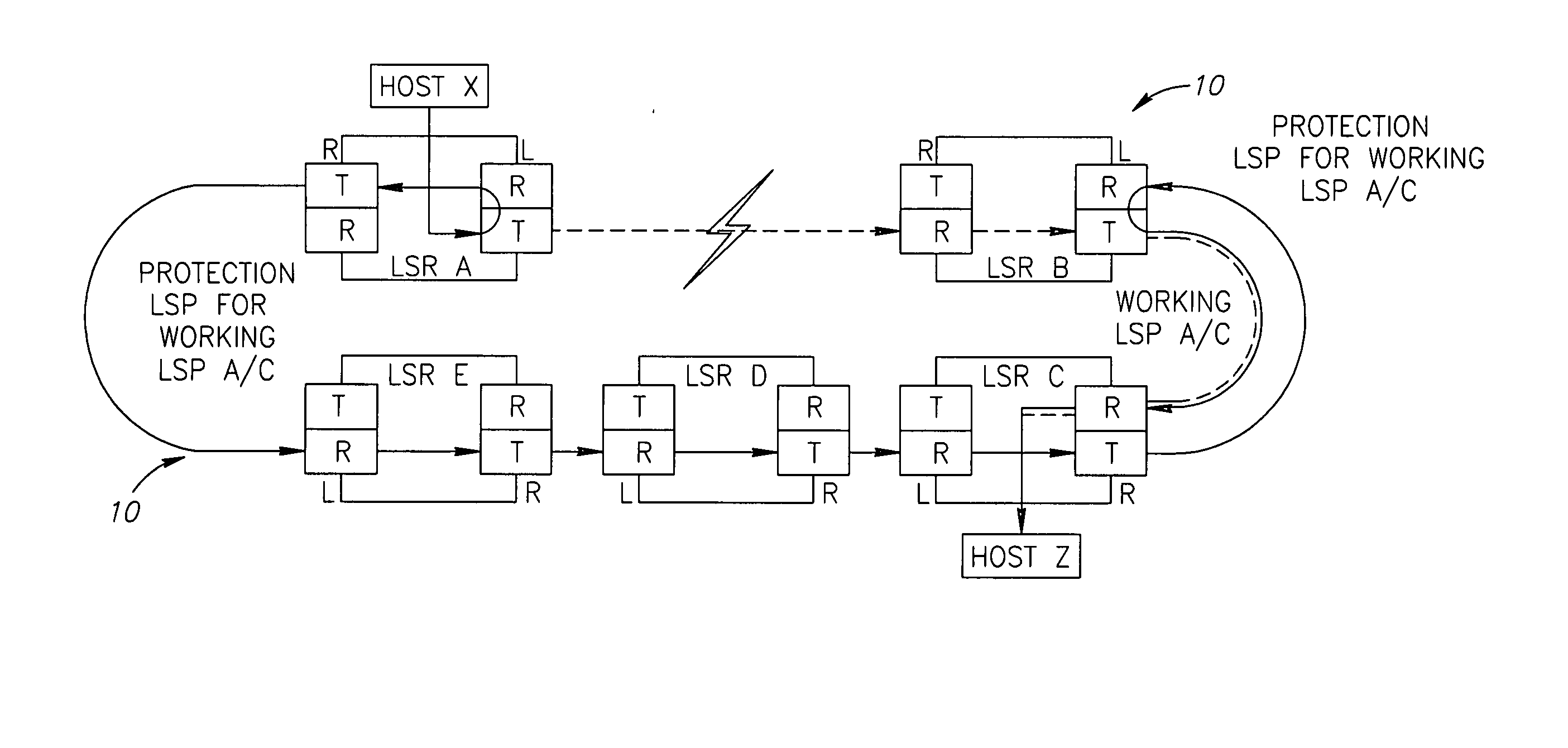
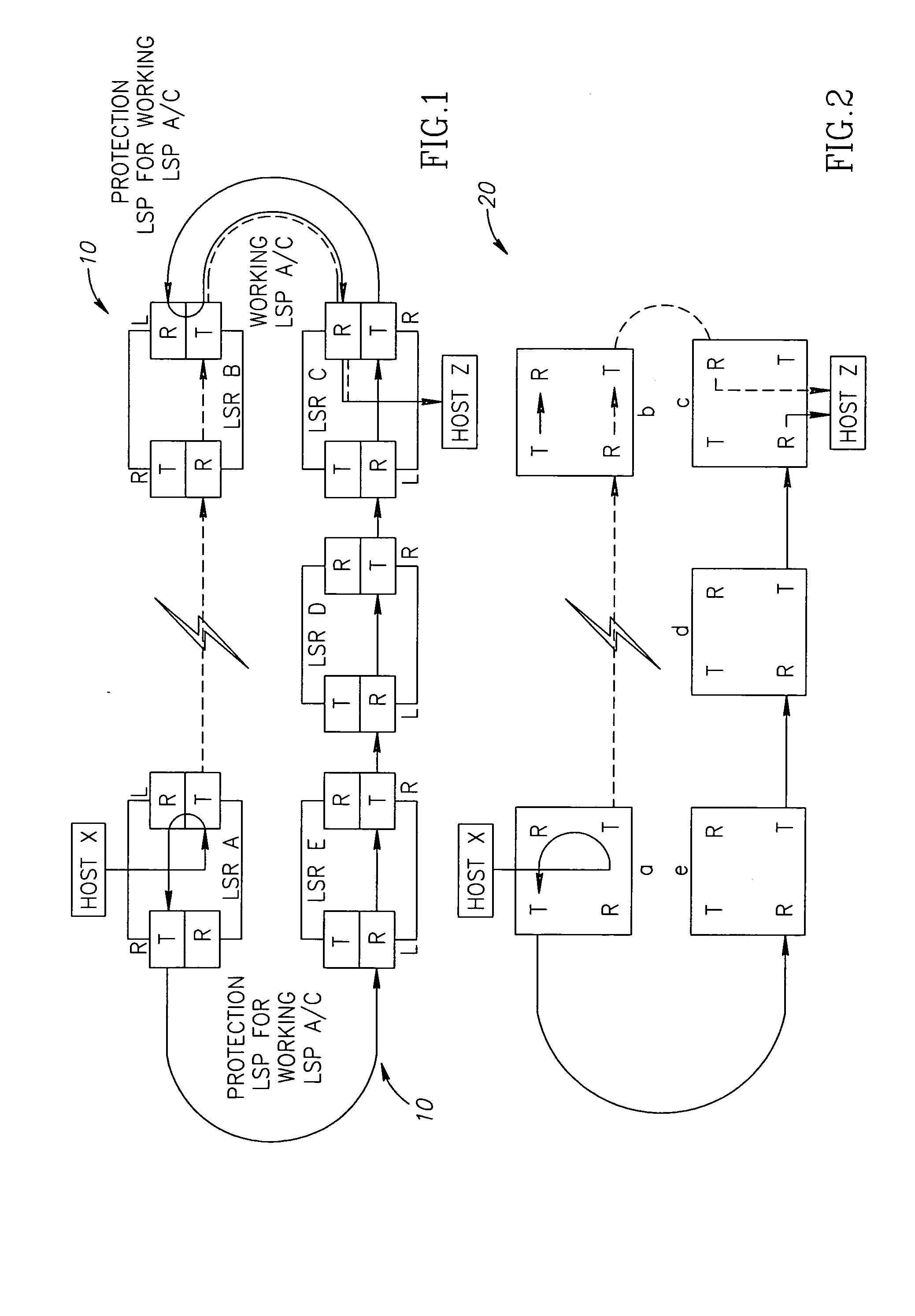
[0051]FIG. 1 shows a schematic route of redirected MPLS traffic in a ring network, as known from the prior art and in particular from US 2003 / 0108029 A1. As can be seen from the drawing, Host X associated with node A (LSR A) of a ring network 10 was in communication (the dotted line) with Host Z associated with node C (LSR C) of the ring 10 before occurrence of a fault (such as a fiber cut, marked as a lightning) between the nodes LSR A and LSR B. The main (working) path of a particular traffic flow (LSP) between the nodes A-B-C was allocated in the inner ring, a portion of which is shown by the dotted line and indicates the working LSP. After the fault, the LSP is redirected at the node A (LSR A) to a protection LSP A-E-D-C-B allocated in the outer (protection) ring and shown with the solid line. The protection path, according to the manner accepted for ring networks, is defined as having a termination point at node B, so the traffic follows till node B without checking it at inter...


PUM


Abstract

A method is described for fast rerouting, in case of a fault, packets of MPLS traffic in a ring-like network configuration, where the MPLS traffic is formed by one or more Label Switched Paths (LSPs) entitled to protection. The method comprises rerouting the MPLS packets to a protection path in the ring, providing the rerouted MPLS packets with additional labels to their respective label stacks, and then detecting the additional labels at network nodes included in the protection path. Detection of the additional labels further allows determining egress nodes of the rerouted MPLS packets and outputting the rerouted MPLS packets at their corresponding egress points from the protection path.

Description

FIELD OF THE INVENTION [0001] The present invention relates to the field of communications, more particularly to the field of rerouting / protecting of so-called MPLS (multi-protocol label switching) traffic in networks comprising rings. BACKGROUND OF THE INVENTION [0002] The problem of rerouting / protecting traffic in communication networks is one of the main topics, which is being permanently discussed and developed to improve efficacy of networks operation. [0003] Ring networks have largely evolved in local area computer networks (LANs). Their main benefits are: ability to add / drop local data to / from the ring at any local station while passively forwarding traffic which doesn't belong to a particular local station; efficient use of cables, for example in comparison with mesh networks; fault recovery of traffic, since two-way links between stations can be used for redirecting the traffic in case of a cable break. SDH / SONET networks have adopted these advantages to implement multi poi...

Claims


Application Information

Patent Timeline
Patent Type & Authority Applications(United States)
IPC IPC(8): H04L12/437H04L12/56
CPCH04L12/437H04L45/00H04L45/50H04L45/28H04L45/22
Inventor NAKASH, SHAUL
Owner ECE TELECOM LTD
Learn More