Method of monitoring equipment of an agricultural machine

a technology of monitoring equipment and agricultural machines, applied in agricultural machines, applications, instruments, etc., can solve problems such as poor performance of agricultural machines, and achieve the effect of fast identification

Inactive Publication Date: 2005-05-05
DEERE & CO
View PDF14 Cites 36 Cited by
  • Summary
  • Abstract
  • Description
  • Claims
  • Application Information

AI Technical Summary

Benefits of technology

[0008] The object of the present invention is to provide an improved monitoring equipment of an agricultural implement which is capable of sending fault messages to a remote station. The monitoring equipment should allow a fast identification of the error at the remote station. Further, notice should not only be given when faults of operative parts occur, but also when the performance of the agricultural machine is too poor.

Problems solved by technology

Further, notice should not only be given when faults of operative parts occur, but also when the performance of the agricultural machine is too poor.
When such as fault or error occurs, the process computer submits a fault message to a remote station using a communications interface.

Method used


Image

  • Method of monitoring equipment of an agricultural machine
  • Method of monitoring equipment of an agricultural machine
  • Method of monitoring equipment of an agricultural machine

Examples


Embodiment Construction

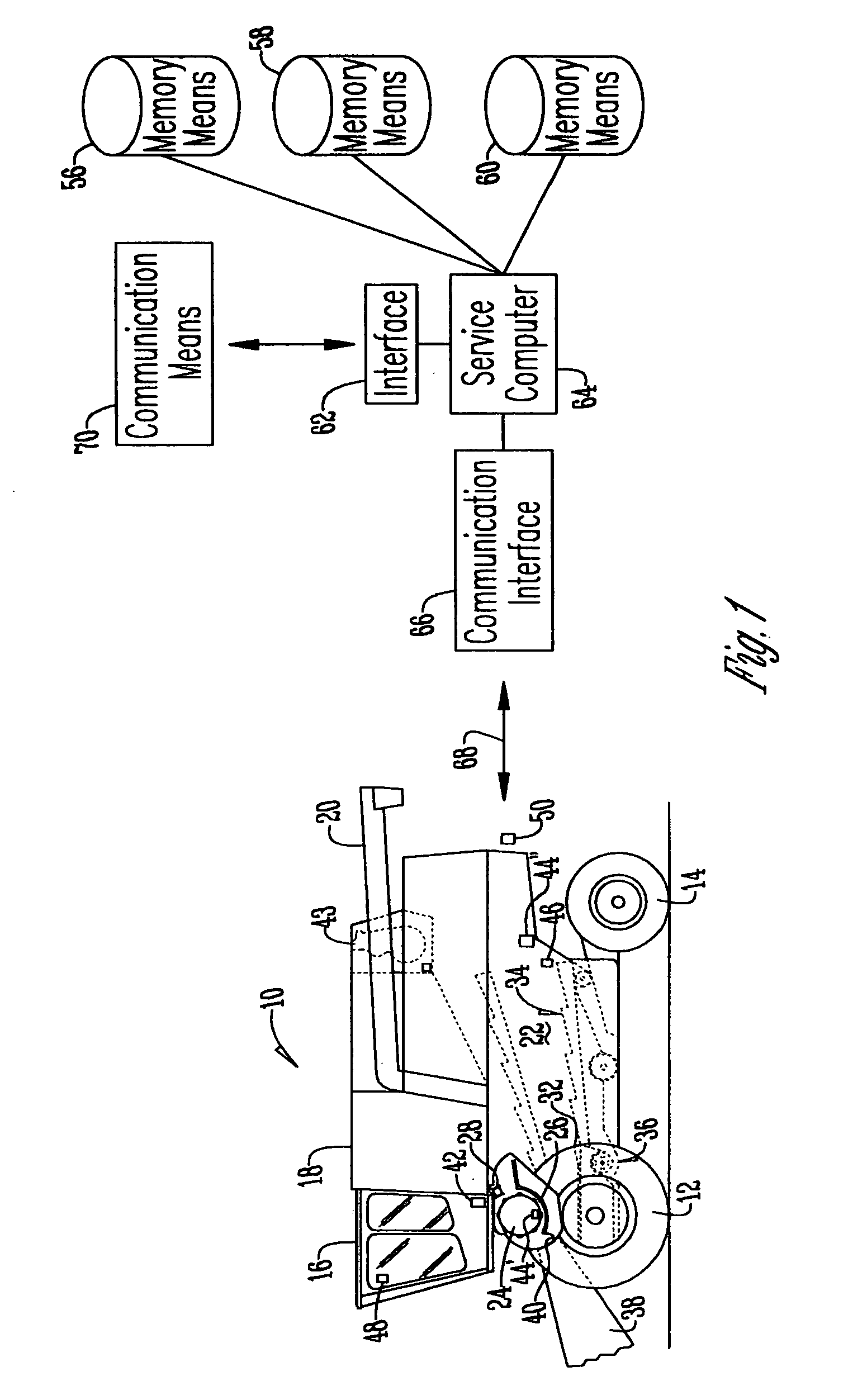
[0018] In FIG. 1, a self-propelled agricultural combine 10 is shown as an example for an agricultural vehicle. The combine 10 is supported on front and rear wheels 12 and 14. The combine 10 is provided with an operator's cab 16 from which an operator can control it. The operator's cab is followed to the rear by a grain tank 18 that can deliver grain deposited in it through a discharge pipe 20 to the outside. The grain tank 18 is supported on a frame 22, in which crop conducted into it is threshed to remove grain from crop residue as the crop is moved in its path past a threshing cylinder 24, a threshing concave 26 and a beater 28. Straw walkers 30 follow the beater 28, as well as a pan 32 and sieves 34, further separate the harvested crop, whereupon finally the threshed-out part of the crop, typically the clean grain, is conveyed into the grain tank 18. The crop residue, i.e. straw, is conveyed over the straw walkers 30 into a rear hood of the combine 10 where it falls onto the grou...


PUM


Abstract

A method of monitoring equipment of an agricultural machine includes taking a process computer and connecting the same to at least one sensor measuring an operational characteristic of the agricultural machine. The process computer evaluates the data received from the sensor and checks whether they indicate a fault of the agricultural machine. In this case, the data may be below and/or above a predetermined threshold. When such as fault or error occurs, the process computer submits a fault message to a remote station using a communications interface. The fault message contains a fault information identifying a type of the fault.

Description

CROSS-REFERENCE TO RELATED APPLICATIONS [0001] This is a continuation-in-part of U.S. patent application Ser. No. 09 / 780,105, filed Feb. 7, 2001.BACKGROUND OF THE INVENTION [0002] 1. Field of the Invention [0003] The invention refers to a monitoring equipment of an agricultural machine, comprising a process computer provided on the agricultural machine, a sensor sensing operational characteristics of the agricultural machine and submitting data containing an information about the sensed characteristics to the process computer, and a communication interface connected to the process computer which is arranged to send fault messages to a station remote from the agricultural machine. [0004] 2. Description of the Prior Art [0005] In the German journal BMT Baumaschine+Bautechnik 11-42(1996), page 46 so-called tele service systems are described, allowing a remote diagnosis, service and control of machines. Thus, data concerning operational characteristics of a machine are sent wirelessly t...

Claims


Application Information

Patent Timeline
Patent Type & Authority Applications(United States)
IPC IPC(8): A01B63/00A01B79/00A01D41/127G07C5/00G08G1/123
CPCA01B63/00A01B79/00G08G1/205A01D41/127G07C5/008A01B79/005
Inventor MAHONEY, BRIAN J.COLVIN, STEVEN L.RUTZ, ARNOLDLANG, STEPHEN
Owner DEERE & CO
Why Eureka
Try Eureka