
Heat treated profile extruded hook

a technology of extrusion and heat treatment, which is applied in the direction of snap fasteners, bandages, buckles, etc., can solve the problems of limiting the individual hook, limiting the strength of the engaging head portion of the hook element, and limiting the strength of the individual hooks, so as to increase the extent of molecular orientation and increase the degree of hook member or projection shrinkage

Inactive Publication Date: 2005-05-12
3M INNOVATIVE PROPERTIES CO
View PDF57 Cites 12 Cited by
  • Summary
  • Abstract
  • Description
  • Claims
  • Application Information

AI Technical Summary

Benefits of technology

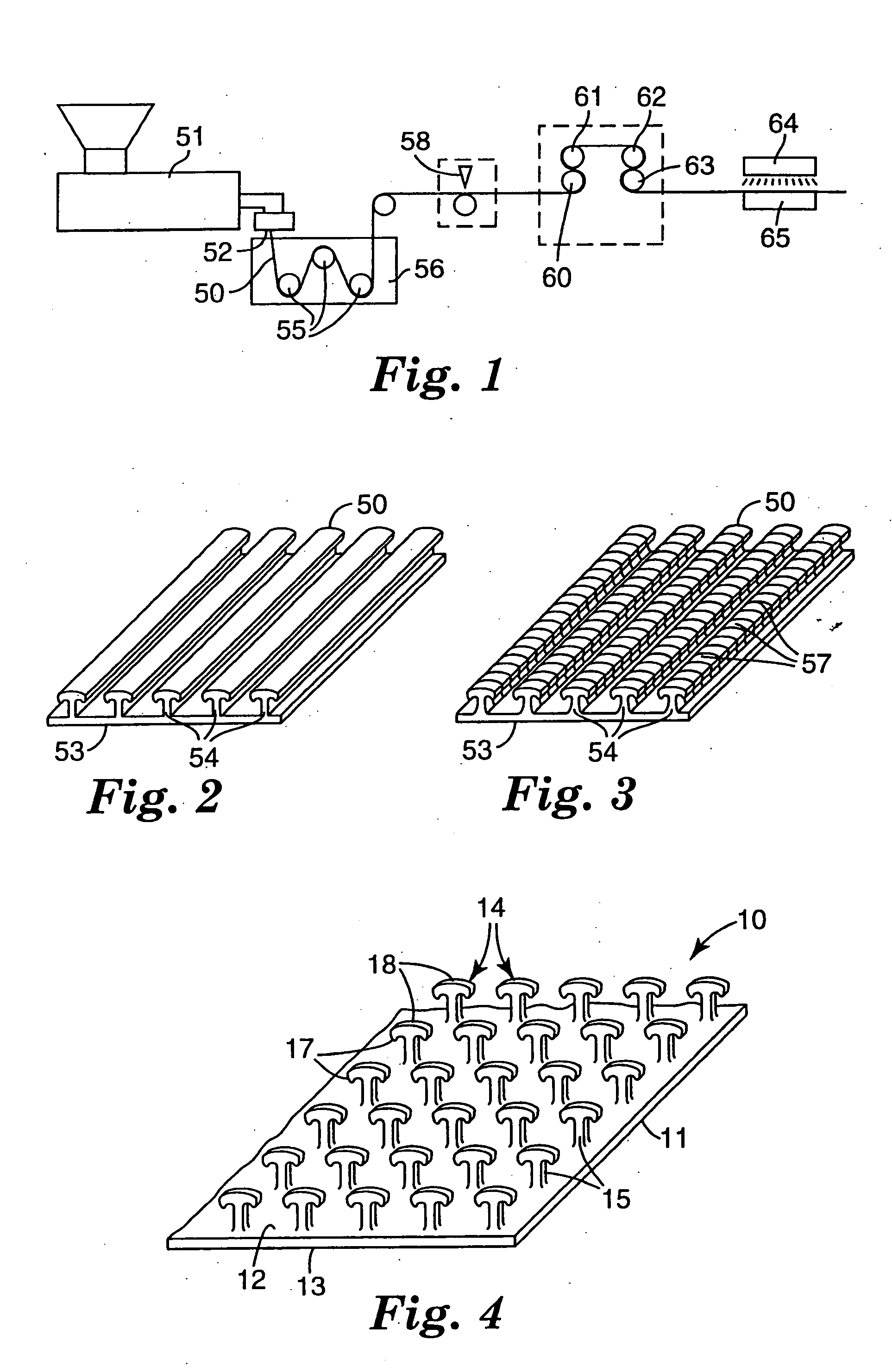
[0007] The fastener is preferably made by a novel adaptation of a known method of making hook fasteners as described, for example, in U.S. Pat. Nos. 3,266,113; 3,557,413; 4,001,366; 4,056,593; 4,189,809 and 4,894,060 or alternatively U.S. Pat. No. 6,209,177, the substance of which are incorporated by reference in their entirety. The preferred method generally includes extruding a thermoplastic resin through a die plate which die plate is shaped to form a base layer and spaced ridges, ribs or hook elements projecting above a surface of the base layer. These ridges generally form the cross-section shapes of the desired projection to be produced, which is preferably a hook member. When the die forms the spaced ridges or ribs the cross sectional shape of the hook members are formed by the die plate while the initial hook member thickness is formed by transversely cutting the ridges at spaced locations along their lengths to form discrete cut portions of the ridges. Subsequently longitudinal stretching of the backing layer (in the direction of the ridges on the machine direction) separates these cut portions of the ridges, which cut portion then form spaced apart hook members. The extruded hook members or cut rib hook members are then heat treated resulting in shrinkage of at least a portion of at least the hook head portion thickness by from 5 to 90 percent, preferably 30 to 90 percent. In an alternative embodiment, the heat treatment is continued to likewise shrink at least a portion of the stem portion of the hook members. The resulting heat treated projections, preferably hooks, are substantially upstanding or rigid such that they do not droop toward the base layer or are able to penetrate a fibrous or like substrate. In a particular preferred embodiment, the extruded thermoplastic resin contains an immiscible phase to increase the extent of molecular orientation in the thermoplastic polymer or increase the degree of hook member or projection shrinkage when heat treated.

Problems solved by technology

However, they are generally expensive and coarse to the touch.
This generally inherently limits the individual hooks to those capable of engaging only in a single direction while also limiting the strength of the engaging head portion of the hook element.
However, a limitation with this method of manufacture is in forming hook structures that are extremely narrow in the extrusion direction of the ribs or the cut direction.
Cutting the formed ribs at very closely spaced intervals is difficult at commercially acceptable production speeds.
Further, when the cut length is extremely closely spaced the previously cut portions of the ribs tend to fuse due to the heat created by the cutting operation.

Method used


Image

  • Heat treated profile extruded hook
  • Heat treated profile extruded hook
  • Heat treated profile extruded hook

Examples


example 1

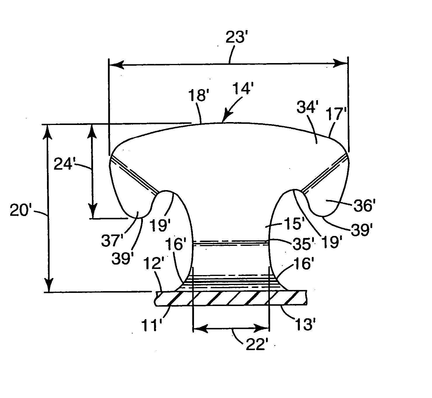
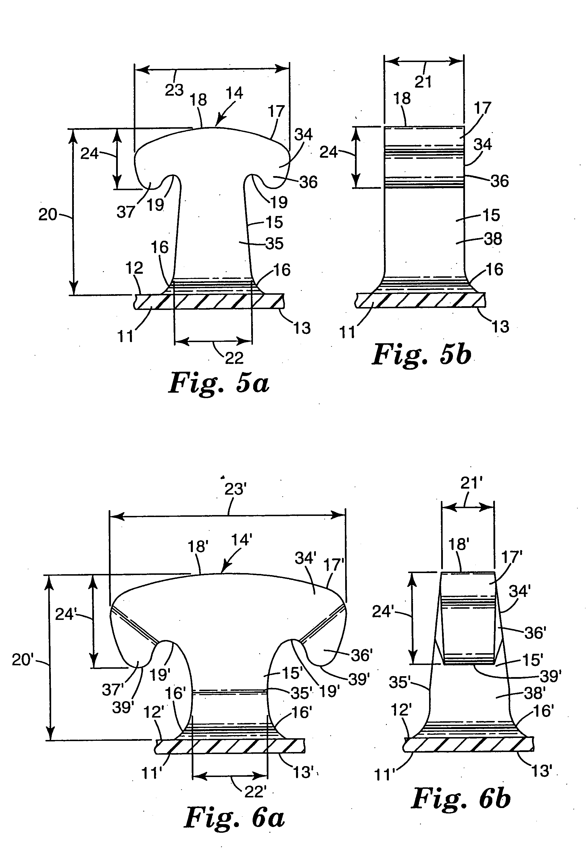
[0075] The web of comparative example C1 was subjected to a non-contact heat treatment on the hook side of the web by passing said web underneath a 36 cm wide ribbon flame burner Aerogen (Alton Hampshire, UK) at a speed of 90 meter / minute with a burner to film gap of 8 mm. The flame power was 74 kJ / hour. The smooth base film side of the web was supported on a chill roll maintained at approximately 18° C. The general profiles of the resulting heat treated hook are depicted in FIGS. 6a and 6b. The performance of the hook material web against nonwoven loop material ‘A’ was measured using a 135° peel test with the results shown in Table 1 below. The peel force of the heat-treated web was approximately 63% greater than the non-heated Comparative Example 1.

example 2

[0076] The web of Comparative Example C1 was subjected to a non-contact heat treatment on the hook side of the web by passing said web underneath a bank of 6-1000 watt 1 micron wavelength infrared bulbs at a speed of 2.1 meter / min. The hook to bulb spacing was approximately 2.5 cm. The smooth base film side of the web was supported on a chill roll maintained at approximately 66° C. The general profiles of the resulting heat treated hook are depicted in FIGS. 7a and 7b. The performance of the hook material web against nonwoven loop material ‘A’ was measured using a peel test with the results shown in Table 1 below. The 135° peel force of the heat-treated web was approximately 206% greater than the non-heat treated Comparative Example C 1.

example 3

[0078] The web of Comparative Example C2 was subjected to a non-contact heat treatment on the hook side of the web by passing said web underneath a bank of 6-2000 watt 1 micron wavelength infrared bulbs at a speed of 3.0 meter / min. The hook to bulb spacing was approximately 1.6 cm. The smooth base film side of the web was supported on a chill roll maintained at approximately 66° C. The performance of the hook material web against nonwoven loop material ‘A’ was measured using a peel test with the results shown in Table 1 below. The 135° peel force of the heat-treated web was approximately 37% greater than the non-heat treated Comparative Example C2.


PUM

PropertyMeasurementUnit
thicknessaaaaaaaaaa
heightaaaaaaaaaa
widthaaaaaaaaaa

Abstract

A method for forming a unitary polymeric projection or fastener comprising a thin, strong flexible backing, and a multiplicity of thin spaced hook members projecting from the upper surface of the unitary backing the method generally including extruding a thermoplastic resin through a die plate which die plate is shaped to form a base layer and spaced ridges, ribs or hook elements projecting above a surface of the base layer. When the die forms the spaced ridges or ribs the cross sectional shape of the hook members are formed by the die plate while the initial hook member thickness is formed by transversely cutting the ridges at spaced locations along their lengths to form discrete cut portions of the ridges. Subsequently longitudinal stretching of the backing layer (in the direction of the ridges on the machine direction) separates these cut portions of the ridges, which cut portion then form spaced apart hook members. The extruded hook members or cut rib hook members are then heat treated resulting in shrinkage of at least a portion of at least the hook head portion thickness by from 5 to 90 percent, preferably 30 to 90 percent.

Description

[0001] This is a continuation-in-part of application Ser. No. 10 / 411,042, filed Apr. 10, 2003, which is a continuation-in-part of application Ser. No. 10 / 316,686, filed Dec. 11, 2002 (now abandoned), which is a continuation-in-part of application Ser. No. 10 / 214,051, filed Aug. 7, 2002 (now abandoned), which is a continuation-in-part of application Ser. No. 10 / 050,403, filed Jan. 15, 2002 (now abandoned), the disclosures of which are incorporated herein by reference.BACKGROUND AND SUMMARY [0002] The present invention concerns molded hook fasteners for use with hook and loop fasteners. BACKGROUND OF THE INVENTION [0003] There are a variety of methods known to form hook materials for hook and loop fasteners. One of the first manufacturing methods for forming hooks involved weaving loops of monofilaments into a fibrous or film backing or the like followed by cutting the filament loops to form hooks. These monofilament loops were also heated to form headed structures such as disclosed i...

Claims


Application Information

Patent Timeline
Patent Type & Authority Applications(United States)
IPC IPC(8): A44B18/00A61F13/62B29C48/00B29C48/08B29C48/12
CPCA44B18/0049A44B18/0065A61F13/62B29C47/00Y10T24/2783B29C47/003Y10T24/2792Y10T24/27B29C47/0021A61F13/625B29C48/00B29C48/08B29C48/12A44B18/00
Inventor AUSEN, RONALD W.UNRUH, WILLIAM C.MILLER, PHILIPSETH, JAYSHREE
Owner 3M INNOVATIVE PROPERTIES CO
Learn More