Rail joint bars and rail joint assemblies

a technology of rail joints and rail joints, which is applied in rail joints, constructions, ways, etc., can solve the problems of compromising the integrity of materials and high cost of non-metallic joints

Active Publication Date: 2005-05-12
KOPPERS DELAWARE INC
View PDF6 Cites 15 Cited by
  • Summary
  • Abstract
  • Description
  • Claims
  • Application Information

AI Technical Summary

Benefits of technology

[0011] The present invention provides for a rail joint assembly that includes a pair of abutting railroad rails having a gasket compressed therebetween and a pair of rail joint bars as previously described secured to the pair of railroad rails by fasteners. The electrically-insulating spacers are positioned between the first rail joint bar and the second rail joint bar resting against the first side and the second side of the abutting railroad rails, respectively. Spacers positioned between each rail joint bar and surfaces of the ab...

Problems solved by technology

However, the non-metallic joints are very expensive due to the special high-performance material needed to endure the high tensile and flexural forces exerted on a rail joint as the wheels of a locomotive or rail car pass ov...

Method used


Image

  • Rail joint bars and rail joint assemblies
  • Rail joint bars and rail joint assemblies
  • Rail joint bars and rail joint assemblies

Examples


Embodiment Construction

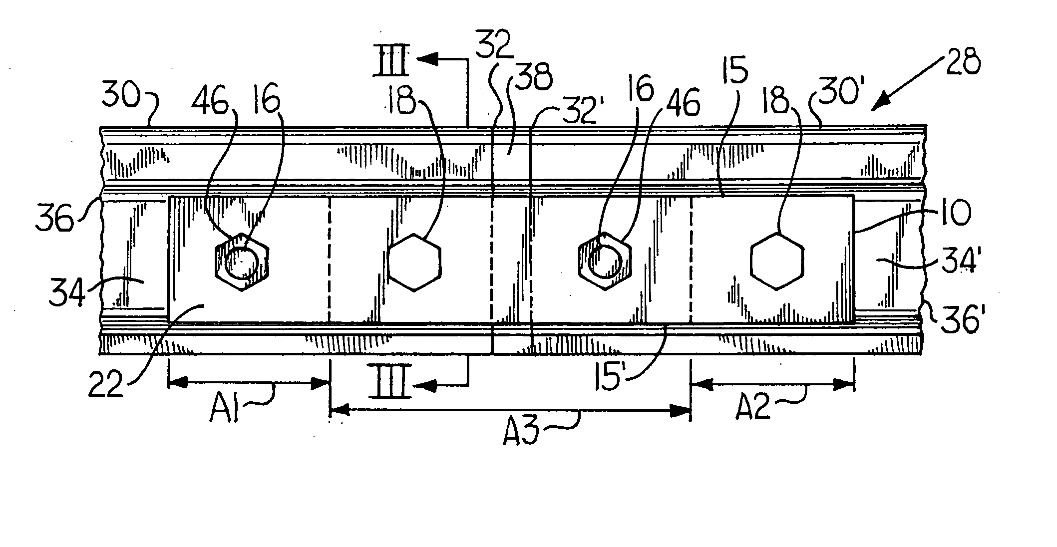
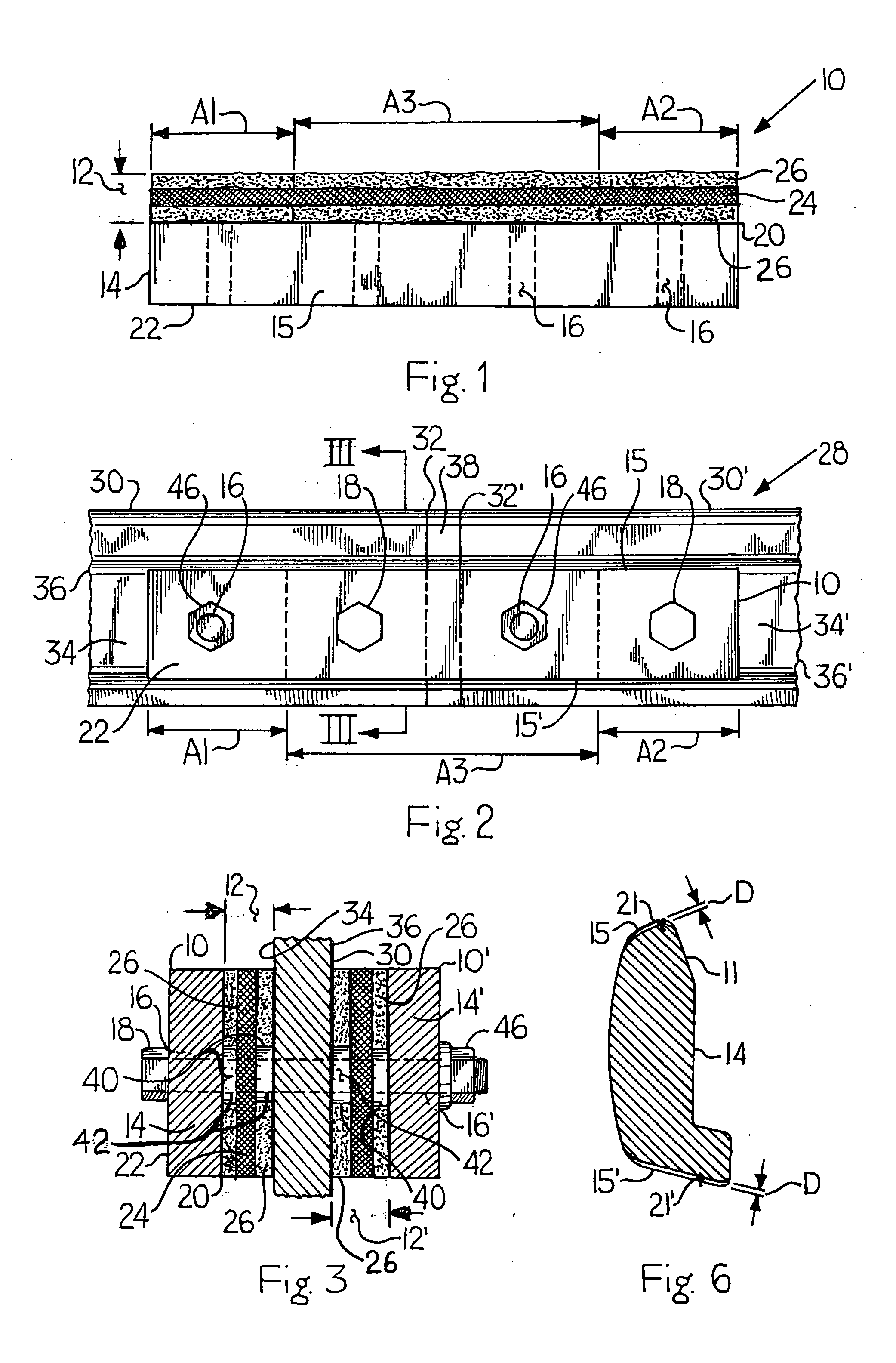
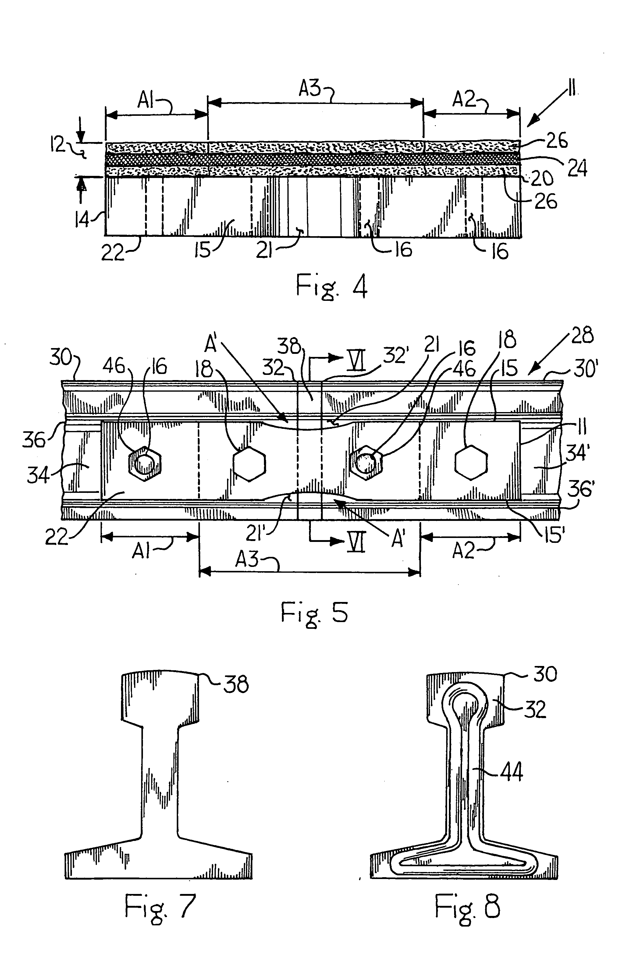
[0024] Referencing FIGS. 1 and 2, the present invention is a rectangular-shaped rail joint bar 10 that includes an electrically-insulating layer 12 bonded to a metal body 14. A plurality of holes 16 (shown in phantom) is defined on the rail joint bar 10, wherein the plurality of holes 16 is adapted to receive fasteners 18 for securing the rail joint bar 10 to two adjacent railroad rails 30, 30′. Referencing FIGS. 1 and 2, the body 14 having an upper end 15, a lower end 15′, a first surface 20 and a second surface 22 is manufactured from metal material, such as steel or similar strength metal.

[0025] Referencing FIGS. 1 and 3, the insulating layer 12 on the rail joint bar 10 is affixed to or coacts with the first surface 20 of the body 14. The first surface 20 of the body 14 can be peened to create a more secure attachment of the insulating layer 12. Optionally, the first surface 20 and / or the second surface 22 of the body 14 is peened. In reference to the present invention, the word...


PUM


Abstract

A rail joint assembly is provided for joining abutting railroad rails with an electrically-insulated joint. The rail joint assembly comprises abutting railroad rails compressing an insulating gasket therebetween and rail joint bars secured through a plurality of holes by fasteners to the adjacent railroad rails. The rail joint bars comprise a body and an insulating spacer comprising a porous mesh screen and washer. A layer of epoxy is sandwiched between a rail joint bar and railroad rail and comprises a rigid epoxy on lateral portions of a first side of a rail joint bar and a flexible epoxy placed on a central portion of the first side of a rail joint bar. Rail joint bars are rectangular shaped and may have a cutout.

Description

CROSS REFERENCE TO RELATED APPLICATION [0001] This application claims the benefit of U.S. Provisional Application No. 60 / 467,451, entitled “Epoxies for Bonded Rail Joints,” filed on May 2, 2003, which is incorporated by reference.BACKGROUND OF THE INVENTION [0002] 1. Field of the Invention [0003] The present invention relates to a rail joint bar and a rail joint assembly for electrically-isolating sections of rail in a rail system. Particularly, the present invention relates to rail joint bars secured by fasteners to abutting rails of a rail system for creating a rail joint having an electrically-insulating spacer between the rail joint bars and rails, and gaskets between ends of the adjacent railroad rails, all for electrically-isolating adjacent rail sections of a rail system. [0004] 2. Description of Related Art [0005] A rail system, which permits more than one train to travel on one stretch of track or rail, is generally divided into sections or blocks. The purpose of dividing r...

Claims


Application Information

Patent Timeline
IPC IPC(8): E01B11/04E01B11/54
CPCE01B11/04E01B11/54
Inventor URMSON, W. THOMAS JR.MOSPAN, JOHN W.DOWNEY, JOHN M.
Owner KOPPERS DELAWARE INC
Why Eureka
Try Eureka